The switchless combiner.
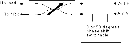
The switchless combiner is a device with two inputs and two outputs. Read about it hereBasic configuration
When used for polarization control one of the inputs is unused. The setting of the combiner will connect the used input to one or the other antenna or to both. Between the combiner and the antennas there is a switchable 90 degree phase shifter.
When the phase shifter at output of the switchless combiner
is set to 90 degrees linear polarization is obtained.
When it is set to zero one can get circular polarization
by setting the combiner to deliver equal power to both
antennas. Both left and right hand circular is possible.
All linear polarisations from 0 to 180 degrees will be possible
if the phase shifter inside the switchless combiner can
be set to phase shifts from 0 to 360 degrees.
The cable lengths have to compensate for any offset between
the antennas. It is the field in free space in front
of the antenna generated by the two outputs of the combiner
that should be either in phase or 90 degrees out of phase.
The simple configurations below have a fixed 90 degree phase
shifter and they can therefore only generate linear polarization.
Practical minimum configuration

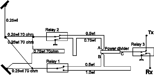
Simple polarisation control for linear polarisation in 45 degree steps. Lines not marked with impedance are 50 ohms.
With two relays, the phase difference at the input of the second hybrid of the switchless combiner can be set at -90, 0, +90 and 180 degrees, which leads to linear polarisation in steps of 45 degrees. For transmit, I see no reason to use finer steps. The phase shifter is the same as the one used to get two linear and two circular polarisations with simple polarisation switching. Look here for power limitations and high power alternatives
One of the power dividers and the 180 degree phase line of the hybrid near Rx/Tx is unused and can be omitted as illustrated in this example.
If the 70 ohm lines constituting the hybrid nearest the antenna is replaced by 50 ohm lines, an impedance transformation will take place. To match, the antenna impedance has to be 25 ohms, which fits perfectly for large arrays where two 50 ohm cables feed the left and right half of the array. Just connecting them in parallel gives 25 ohms, so the whole system can be designed with 50 ohm lines. Of course both of the cables for one polarisation will then have to be a quarter wave longer than the two cables for the other polarisation.
Dual channel receive systems with a switchless combiner for Tx

When a sophisticated system with two receiver channels is used, it is a good idea to place the antenna relays in front of the polarisation control system used for transmitting. In this way the receive and transmit systems become independent. On the receive side continuos rotation of the polarisation plane may be arranged by a switchless combiner and an electronic phase shifter or with a potentiometer and a pair of balanced mixers
To have circular polarisation on transmit, one or two relays may be used to remove the quarter wave line difference in feed line between the antennas and the switchless combiner.
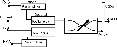
Dual channel receive systems with a common switchless combiner for Rx and Tx

If the switchless combiner is arranged to switch the polarisation in steps of 22.5 degrees (or finer) there is not much reason to have a separate polarisation control for the receiver. Still it is a good idea to use two preamplifiers in order to bring two orthogonal polarisations down to the schack. By monitoring the B signal on a FFT spectrum analyser, like FFTDSP by AF9Y, it is much easier to select the correct receive polarisation by tuning for minimum in the B signal than by tuning for maximum on the A signal.
To have circular polarisation on transmit, one or two relays may be used to remove the quarter wave line difference in feed line between the antennas and the switchless combiner.
To SM 5 BSZ Main Page