The switchless combiner - a useful device
This device is used for example in professional broadcasting in order to switch over from one transmitter to another for servicing. It allows a continuos switching at full power.

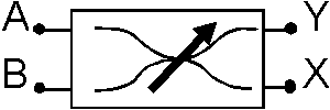
Fig 1, symbolic representation for the switchless combiner
If two identical transmitters are connected to A and B, and a dummy load and an antenna are connected at the X and Y ports, the power to the antenna is independent of the combiner setting. When the combiner is set at one end position, the A transmitter delivers all power to the antenna, and when the combiner is set at the other end position, the B transmitter is connected to the antenna.
In the end position the transmitter not connected to the antenna is connected to the dummy load and can be switched on and off without affecting the signal transmitted by the antenna. In intermediate settings, the power at the antenna will come from both transmitters.

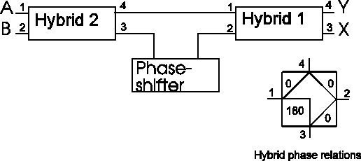
Fig 2. The switchless combiner is made up from 2 hybrids and a variable phase shifter.
The hybrid
A hybrid is four port device. It is commonly used to connect two power amplifiers to a common antenna in order to double the power, while isolating the amplifiers from each other for protection in case one of them fails.

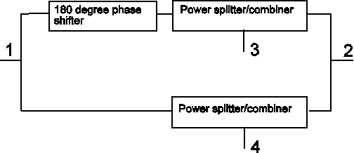
Fig 3. Equivalent schema of the hybrid. The lines connecting the different parts must be kept very much shorter than a quarter wavelength.
The hybrid may be seen as a device with the circuit diagram shown in fig 3. It may be designed from transformers or bought as an encapsulated device from e.g. Mini-Circuits. For use as a part in a polarisation control system it is best designed from transmission line segments. Then, power handling requirements are easily met and limited bandwidth is no problem.
Fig 3 is intended to explain how the hybrid works. Understanding the hybrid allows its use as an impedance transformer, so with some easy modification it may become a part of the matching harness for an antenna array, at the same time as it allows polarisation control, making the total system simpler.
How the hybrid works
Refer to fig 3: When power is fed into port 1, half of it goes the upper way, and the other half goes the lower way. The impedance at a is 50 ohms, so the upper and lower paths must have an impedance of 100 ohms. If the loads at 3 and 4 are identical, the signals coming out at the right hand side of the power splitters/combiners will be equal in amplitude and opposite in phase. When they meet at 2, their voltages will cancel and their currents will add. With zero voltage at port 2 no power will come out there when the load is 50 ohms. As seen from ports 3 or 4, port 2 is a short to ground because there is no voltage there.The power splitters/combiners are perfectly happy with a short to ground at port 2. This short circuit is transformed inside. All the power coming from 1 into the lower power splitter/combiner, leaves through port 4. The signal travelling via 2 to port 3 has no power; at 4 the voltage is large but the current zero, while at 2 the current is large and the voltage zero. When using transmission lines, the power splitters/combiners have to be made from quarter wave sections of square root (50*100) ohm = 70.7 ohm cable to make the hybrid work for 50 ohms at all ports.
When power is fed into port 1, it is split into two parts coming out through 3 and 4. These signals are equal in amplitude but opposite in phase and contain half the power each. Port 2 is insulated from 1 so the voltage there is independent of whatever signal is fed into port 1.
U3 = - 0.707 * U1
U4 = 0.707 * U1
When power is fed into port 2, nothing will come out at port 1. The signals coming out at 3 and 4 are identical.
U3 = U4 = 0.707 * U2
When power is simultaneously fed into 1 and 2, the two signal sources both see a 50 ohm impedance, but not each other. The signals coming out at 3 and 4 will be:
U3 = 0.707 * ( U2 - U1 )
U4 = 0.707 * ( U2 + U1 )
How the switchless combiner works
Refer to fig 2. Apply a signal at B from a 50 ohm source, and terminate A in 50 ohms. The signals at 3 and 4 of hybrid 2 will be equal in amplitude and phase.If the phase shifter is set at zero - the signals at ports 1 and 2 of hybrid 1 will be equal in amplitude and phase. Their sum will come out at Y, and it is identical to the signal at B, while their difference, which is zero comes out at X.
If the phase shifter is set at 180 degrees - the signals at ports 1 and 2 of hybrid 1 will be equal in amplitude but opposite in phase. Their sum, which is zero, will come out at Y, while their difference, which is identical to the signal at B comes out at X.
For intermediate settings the power is split between X and Y. In what way comes out from some simple mathematics. Apply a sine wave at B:
B = U22 = sin ( w * t ) | Voltage at B
U23 = 0.707 * sin ( w * t ) | Voltages at hybrid 2
U24 = 0.707 * sin ( w * t ) | ports 3 and 4
The phase shift from port 4 on hybrid 2 to port 1 on hybrid 1 is ph0, while the phase shift from port 3 on hybrid 2 to port 2 on hybrid 1 is ph0 + ph, and it depends on the setting of the phase shifter, ph.
U11 = 0.707 * sin ( w * t + ph0 ) | Voltages at hybrid 1
U12 = 0.707 * sin ( w * t + ph0 + ph ) | ports 1 and 2
X = U13 = 0.707 * ( U12 - U11 ) | Voltage at X
Y = U14 * 0.707 * ( U12 + U11 ) | Voltage at Y
Putting in the sine waves for U11 and U12 leads to:
X = ( sin ( w * t + ph0 + ph ) - sin ( w * t + ph0 ) ) / 2
Y = ( sin ( w * t + ph0 + ph ) + sin ( w * t + ph0 ) ) / 2
A standard formula says:
sin( a + b) = sin( a ) * cos( b ) + cos( a ) * sin( b )
Using a = w * t + ph0 + ph/2 and b = ph/2
the standard formula gives:
sin( w * t + ph0 + ph ) =
sin( w * t + ph0 + ph/2 ) * cos( ph/2 ) +
cos( w * t + ph0 + ph/2 ) * sin( ph/2 )
Using a = w * t + ph0 + ph/2 and b = - ph/2
the standard formula gives:
sin( w * t + ph0 ) =
sin( w * t + ph0 + ph/2 ) * cos( - ph/2 ) +
cos( w * t + ph0 + ph/2 ) * sin( - ph/2 )
or after using the symmetry of sine and cosine functions:
sin( w * t + ph0 ) =
sin( w * t + ph0 + ph/2 ) * cos( ph/2 ) -
cos( w * t + ph0 + ph/2 ) * sin( ph/2 )
Now the expressions for X and Y may be rewritten as:
X = cos( w * t + ph0 + ph/2 ) * sin( ph/2 )
Y = sin( w * t + ph0 + ph/2 ) * cos( ph/2 )