The "+" configuration vs the "x" configuration
A cross yagi system may be mounted with any orientation of the elements. It can still be used to produce any desired polarisation. The usual configuration is the "+" with one horizontal part and a vertical. There are good arguments to prefer the "x" configuration with the elements in +45 and -45 degrees angle. It seems like most amateurs believe the "x" configuration is much more complicated, but that is not true at all.On this page you can look at the connection diagrams for simple switch systems for both configurations.
The advantages of using the "x" configuration are:
1. High gain yagi antennas are sensitive to water. A horizontal antenna easily gets water droplets hanging all along the elements, causing the element diameter to increase which detunes the antenna. Losses are also increased. This is no problem for a vertical yagi, on which there will be only one droplet hanging at the end. Antennas in the "x" configuration are also insensitive to rain like a vertical one.
2. In the "x" configuration it is easy to produce circular as well as horizontal and vertical polarisation just by changing the relative cable lengths. Relays used for that will handle only half the power, so even for EME, small standard relays can be used, and if the antennas have separate pre amplifiers, the rx/tx relays only have to handle half the power.
3. With +/- 45 degree elements it is possible to put a second boom tube under the main boom tube to enforce the centre part. This will not affect the electrical properties of the antenna if the separation is reasonable.
4. It is easier to use plastic wires to keep the boom tube straight.
5. In the " x " configuration, poor othogonality leads to poor SWR when the phasing is for horisontal or vertical, but no loss of gain. In the " + " configuration, poor orthogonality leads to loss of gain, when power is fed into one antenna or the other for horisontal or vertical polarisation, but SWR is not much affected. For more info, look here: How to calibrate an adjustable polarisation antenna.
Two relays for the "+" configuration
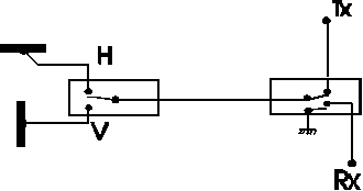
This is the most common solution for use of a cross yagi system. One extra relay is added in order to switch between horizontal and vertical polarisation. Note that no isolation relay is needed between the tx/rx relay and the pre amplifier if the cable between the relay and the pre amplifier is properly selected The length of the other cables makes no difference - but of course short cables will give low losses.
The relay switching between horizontal and vertical needs no high isolation. 20dB isolation is more than enough, so a simple relay, without any short circuit to ground for the unused connector will do perfectly well. A home made relay will do perfectly well on 144MHz.
Two relays for the "x" configuration
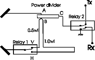
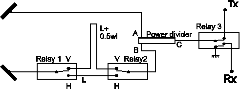
When two antennas are at +/- 45 degrees, they have to be fed with equal voltages and phases to produce horizontal polarisation. By reversing the phase for one of them, polarisation changes 90 degrees, and vertical polarisation is obtained. This can be done with just one relay. From the B port to the relay, there is a continuos 50 ohm feed line to the antenna through the V or H connector of relay 1, whichever of them being in use. To the other one, which is open, the electrical length is one half or a full wavelength. Note that the unused contact must not be shorted to ground because then the B port of the power divider becomes shorted to ground. (If a shorting relay is used, both sides must be shorting, and both cables are then made a quarter wave shorter) In both cases the unused cable will cause no reactive loading at the B port because a N * 0.5wl open stub will be in resonance and have a very high impedance. The power divider could be a quarter wave segment of 35 ohm cable, the impedance at A and B is 50 ohms. The electrical length from A on the power divider to the upper antenna has to be the same as the electrical length from B to the lower antenna +/- N * 0.5wl Which of the positions on relay 1 that will produce horizontal polarisation depends on how the dipoles are oriented and if N is odd or even.
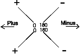
When the phases are as in the figure above, the electric field at some particular moment will look as indicated by the plus and minus signs at the element tips. From some distance the fields from the two dipoles will add to produce a field as indicated by the arrows. This is the field of a horizontal antenna. By turning the picture 90 degrees, you get the picture of a vertical antenna.
Three relays for the "x" configuration
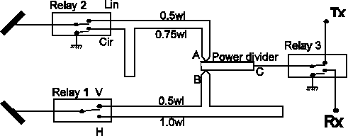
This solution, which gives left and right circular polarisation as well as horizontal and vertical was published in about 1974 by SM5AGM Folke Rosvall in QTC, the Swedish amateur journal. The power divider could be a quarter wave segment of 35 ohm cable, the impedance at A and B is 50 ohms. In order to get circular polarisation, the difference in cable length has to be a quarter wave, and since an open quarter wave (or three quarter wave) can not be connected to the A port since it would be a short circuit, relay 2 has to be of the rx/tx kind, that shorts one of the unused contacts to ground while it leaves the other one open when that is unused. At EME power levels this solution may be risky, look below for alternatives.
High power three relay solution for the "x" configuration
When an open stub is connected, the voltage at the open end will be twice as high as the normal voltage in the transmission line. At 1500W total power, 750 W will go to each antenna. The voltage is then about 200V RMS in the 50 ohm feed lines, so the peak voltage at the open stubs will be about 600V, and that may be too much for simple relays. Connecting relays back to back and operating them in parallel is a way of avoiding this problem. The relays will switch between two cables differing in length by half a wavelength.
High power five relay solution for the "x" configuration

Adding two more relays in order to allow the phase difference to become 90 degrees like in the figure is a trivial extension of the high power three relay configuration. Note that the use of a shorting contact for allowing a quarter wave stub leads to high currents in the shorting contact. The current in the shorting contact is twice the current in the 50 ohm cables to the antennas.