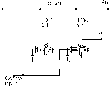
Fig 1. Schematic diagram of high power PIN diode switch.
It is really very straight forward. There is a 50 ohm coax from Tx to antenna. Along this cable there are two T connections separated by one quarter wavelength. At each T a high impedance quarter wave coax cable is connected. This high impedance coax has an inner conductor with a diameter of 3 mm. The outer conductor is taken from a 2 inch 50 ohm cable and the diameter is about 45 mm. Two spacers made from 1 mm teflon hold the centre conductor in place. One near the midpoint and one a few centimeters from the PIN diode. At the T connection the centre conductor is well kept in place by being soldered to the much thicker centre conductor of the 50 ohm cable.
At the end of each high impedance cable there is a PIN diode from the inner conductor to a well decoupled piece of copper to which the DC for the diode is routed. This is for cooling, from an electrical point of view just a good decoupling is needed. (The inductance of the decoupler adds to the diode inductance and is balanced out by a little coil, see below) Practically, a copper plate of something like 60*90 mm is soldered to the end of the outer conductor. A 15 mm hole in it allows the certre conductor to stick out. A copper plate, something like 50*50mm is sitting a few mm above the 60*90 mm plate, at the side, so the diode is soldered with practically no lead length. All the way around the 50*50 mm plate there are decoupling capacitors to distribute the current - they have to take 10 amps RF together, so how many depends on what current each one can take. For transmit, both diodes have 1A forward DC current, and in receive, both diodes have 12V DC backwards.
From the centre conductor at the same point as where the PIN diode is connected, there is a LC circuit for 144MHz, that can be tuned to make the other end of each high impedance quarter wave a really efficient short circuit to ground.
The Rx is connected to a tap on the coil at the PIN diode nearest to the antenna.

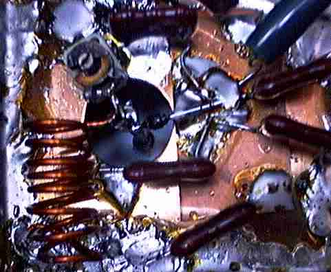
Fig 2. The PIN diode at the transmit side.
The coil (left side low half) has many turns (8) so it is tuned with
a very small capacitor (above the coil).
The impedance is VERY high at this point in receive mode, which
is nessecary to make the impedance VERY low at the other end of the
quarter wave so any noise from the transmitter is well suppressed.
A very high L to C ratio makes the isolation good over a reasonable
bandwidth.
The coil and trimmer capacitor are connected to the 3mm inner conductor
of the 100ohm coaxial line where it enters the little box containing
the components.
Immediately right to the hole is a piece of 1mm thick copper, the purpose of which is to remove heat. The diode is connected to this copper sheet and to the inner conductor with less than 1mm lead lengths.
The 1mm copper sheet (roughly 5 by 5 cm) is hanging in the air a few mm above the box bottom. It is hanging in the diode and several silver mica capacitors spread around the circumference. Together the capacitors give a low inductance path to ground for the current through the diode. Note that the capacitors have to handle several amperes of RF current each. Silver mica was the only "high current" capacitors in my junk box - I would think transistor amplifiers in the 100W range use suitable more modern capacitors for currents in the 10A range.
The resistor in the upper right corner is selected to give 1A bias through the diode when 5V is applied to the control input.

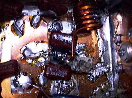
Fig 2. The PIN diode at the receive side.
The design is basically the same as at the transmit side.
The L to C ratio is much lower because the impedance is only 200 ohms
and the coil is used to transform the impedance down to 50 ohms
by a center tap.
The little link used to pick up some magnetic field and create a
nulling out of the voltage caused by the inductance to ground
through the PIN diode and the decoupling arrangement is hidden in the
dark. It goes about 15mm down along the center conductor.
RX MODE:
With 100 ohms impedance in the coax, the impedance becomes 200 ohms at the PIN diode, so a tap halfway up the coil restores 50 ohms. When the Rx is connected, the PIN diode is loaded by 200ohms, so at the other end of the 100ohms quarter wave 50 ohms is obtained. This point will see 50 ohms towards the antenna, and an open circuit towards the transmitter - a quarter wave to the short circuit created by the other open quarter wave.
To check the position of the centre tap, just measure the SWR (low power) of the rx port in receive mode. The reactive part of the impedance is tuned to zero with the tuning capacitor (or the total number of turns). The real part can be adjusted by moving the tap. You may also tune and tap for minimum (=0dB) loss in a 50 ohm lab system. That will give an identical result.
TX MODE:
The PIN diode makes a very good short circuit (0.1 ohms) when 1A is flowing through it. The two quarter wave sections operate in identical fashion in tx mode. The HF power coming from the Tx will see 50 ohms towards the antenna, and 10000/R ohms towards the PIN diode at both T points (R is the resistance of the PIN diode). Other losses are negliable compared to the diode losses.
At 20kW 20A will flow towards the antenna with 1000 volts at each T junction. The diode UM9415 has 0.1ohms at 1A bias so the impedance at the T junction is transformed to 100000 ohms due to the quarter wave section of 100 ohm line. The power lost in the diode is then 10W because all the power lost in the 100000 ohm load is lost in the PIN diode. (1000 volts over 100000 ohms transforms to 1 volt over 0.1 ohms with a 100 ohm quarter wave transmission line.)
For UM9415 10 W is permitted if both leads are extremely short and kept below 50 degrees C, which is not really a problem. The unit should allow at least 20kW continuos wave, and much higher peak powers at SWR=1.00. At SWR=4 the current through the diode may reach 10A at a power level of 5kW. There is plenty of margin for this PIN diode switch even when the antenna is detuned by wet ice.
(Thanks to Steve Harrison, KO0U the old and incorrect power rating of max 5kW at SWR=1 is replaced by the above - Oct 01 1998)
The UM9415 diode is manufactured by Microsemi They have an excellent booklet PIN Diode Designers' Handbook describing the use of PIN diodes for various purposes including phase shifters and high power switches (30kW).
If the diodes are not backwards biased, the loss for Rx is about 0.5 dB, because the resistance is about 1.5kohms at zero volts. With 12V backwards bias, the resistance is maybe 5 times higher and the losses in Rx mode is maybe 0.1dB. The reverse current causes no measurable noise in the Rx path. The carrier life time is very long, 2microseconds, so noise is not produced at VHF - or at least - I can not measure it.
To make the isolation from the transmitter better, there is a small coil connected between the LC circuit to which the rx is connected and the PIN diode. This coil is made from 10 mm of wire, and couples to the current flowing through the diode. It balances the voltage due to the inductance of the diode.
The GAS FET preamp is connected directly to the PIN diode switch with no additional protection. Note that the cable length between the PIN diode switch and the preamp is important. At full power I get about 1 volt rms across a 50 ohm resistor if I connect it instead of the preamp. This one might think is only 20 mW and not any problem. BUT if a 1 ohm resistor is connected, with a cable of an electrical length of a half wavelength, the voltage is still the same, and the power is then 1W - the PIN diode switch is a source of a very low impedance at the rx port in transmit mode (Like all shorting relays). When the preamp is driven into saturation the impedance is far from 50 ohms. If the cable length is badly selected too much power may be transferred.
The practical solution is as follows - and it may be useful also if you use normal relays for rx/tx switching. I assume a GAS-fet is used as the active component.
1. Switch off the DC voltage to the GAS-fet at the same time as the current through the PIN diodes is switched on. There is no need to heat the chip with power from drain current.
2. When you have verified that the tx/rx switch does not give more than say 5 volts in a 50 ohm resistor at full output power, lower the power by 20dB and connect the preamp. Measure the voltage across the source resistor, which gives the gate current - remember, no DC to the drain. If you can not see any gate current, increase power until you can.
3.Try some different cable lengths between the preamp and the tx/rx switch. For each length, start at low power. There will be a very sharp minimum in the gate current, corresponding to very high power before you see it. That is the correct length to use.
The MGF1502 which I use can take 30mA of gate current for a very long time - but not for ever. I have been running the system for two years before it failed (during the ARRL contest 1996). That was before I realised that the cable length is important. Now the gate current is below 5mA after I inserted a quarter wave more cable. I did not really worry to look for the exact minimum since I think the margin is good enough.