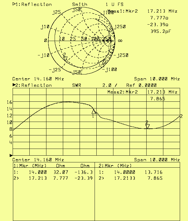
The particular Softrock unit used in the tests on this page.The unit is a Lite+USB Xtall v9.0. It was built by Jan Kuno, K6FM. It is the very unit that Jan Kuno wrote about in QST March 2011, page 60.Sensitivity.The filter I got with the Softrock is for 14 MHz. When listening to a signal at 14.15 MHz using a modified Delta 44 set to -10 dBV I find that the noise floor in 500 Hz is at -124.5 dBm which corresponds to a noise figure of 22.5 dB. Saturation is at -13 dBm (1.07 V rms into the Delta 44) for a dynamic range of 138 dBc/Hz. Setting the Delta 44 to "Consumer" would degrade the noise figure and improve the dynamic range. Reciprocal mixing degrades the dynamic range by 1 dB only at a frequency separation of 10 kHz.A noise figure of 22.5 dB might be adequate on 14 MHz, but the Softrock can do better. Figure 1 shows the input impedance and SWR vs frequency. The match to 50 ohms is not good at all with SWR=13 on 14.16 MHz to which frequency the Si570 is tuned. |

|
|
Fig. 1. The input impedance of the Softrock Lite + USB Xtall
in its original shape. Figure 2 shows the schematic diagram of the input filter. The Softrock Lite + USB bill of materials specifies a fairly wide filter for 30m/20m/17m. The frequency response with a 50 ohm load between 2 and 4 on T1 is shown in figure 3. |

|
|
Fig. 2. The Softrock RF input filter. |

|
|
Fig. 3. The frequency response of the Softrock
in its original shape.
The filter attenuates by 7 dB at 14 MHz. The -10 dB points are at 6 and 20 MHz. This filter might be adequate for many practical purposes, but it seems to me that a narrower filter with better impedance matching would be desireable sometimes. The filter of the Softrock Lite II is narrower. With an adjustment of the T1 secondary winding it provides a very good impedance match as can be seen in figure 4. |

|
|
Fig. 4.
The input impedance of Softrock with the component values
for the Softrock Lite II RF filter but with a transformation
5 to 16 on the output transformer rather than 1 to 1.
The component values for the various filter versions are listed in table 1. |
Filter version       C3     C4     L1      T1  primary   secondary
                    (pF)   (pF)   (uH)  (type) (turns)    (turns)
Lite + USB Xtall    180    220    0.78   T25-6   14         2x7
Lite II              47    680    2.5    T30-6    8         2x4
Opt                  47    680    2.5    T37-6    5         2x7
|
| Table 1. Different filters for 14 MHz. |
|
The optimized filter gives a frequency response as shown in figure 5 when T1 is loaded by 50 ohms between 2 and 3. |

|
|
Fig. 5.
The optimised RF bandpass filter with a 50 ohm load
between 2 and 3 on T1.
The sensitivity is improved significantly by the filter optimization. Saturation is at -20 dBm and the noise figure meter shows 15.5 dB. A little more than 50 % of the noise originates in the Delta 44. Rather than operating it at the -10 dBV setting one can short the 6.8 k resistors in the input attenuators of the modified soundcard and operate it at the +4 dBV setting. This lowers the noise of the soundcard by 3.5 dB while the saturation level remains unchanged. The noise figure at the Softrock antenna connector is then 12.2dB. That means that the noise power is -161.8 dBm/Hz for a dynamic range of 142 dBc/Hz (saturation is still at -20 dBm.) Reciprocal mixing.Figures 6 and 7 show the Linrad screen with Softrock. The signal source is an ultra-pure crystal oscillator. The Delta44 card is modified for best possible performance and its noise contribution is negligible. The computer is a 650 MHz Pentium III running Windows XP. (There are no properly working drive routines for Delta 44 for Vista or Windows 7.) |

|
|
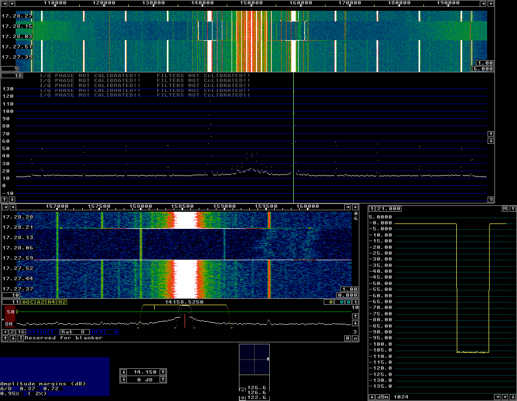
Fig. 7.
The Linrad screen with Softrock.
A near saturating signal is present on 14.1585 MHz.
The level is -20 dBm but the S-meter is miscalibrated
on purpose to show 0 dBm for the strong signal.
|

|
|
Fig. 8.
The Linrad screen with Softrock.
This screen dump differs from figure 7 in that Linrad
is tuned 5 kHz away from the carrier on 14.1585 and
that the zero point of the S-meter is shifted.
We can read directly from figure 8 that the noise floor in 1 kHz bandwidth is 110 dB below the carrier which in turn is 0.78 dB below the point of saturation (lower left corner of the screen.) When the oscillator is stopped the noise falls to 112.2 dB below the carrier. Modern receivers are typically limited by reciprocal mixing. Table 2 shows the blocking dynamic range of Softrock and some conventional receivers on 14 MHz. |
             5kHz   20kHz   100kHz   500kHz
Softrock      141    142     149      156
IC706MKIIG    114    127     140      149
IC7800         -     143     157      162
TR7A          113    120     141      146
TS2000        103    129     145      157
|
| Table 2. BDR (blocking dynamic range) of Softrock and some conventional receivers. |
Close range spurs.The noise floor of the Softrock is really good, but there are other limitations that we do not find in conventional receivers.From figure 7 or 8 we can see the mirror image spur at 14.1415 MHz 24 dB below the main signal. The mirror image can be balanced in hardware or software. The spurs that are visible in figures 7 and 8 are listed in table 3. |
                                       --------- Level -----------
  Origin       Frequency    Audio     Fig 7   LP filter    LP-10dB
                  (MHz)      (kHz)     (dB)     (dB)        (dB)
Signal          14.15855     8.55       0         0         -10
Mirror          14.14145     8.55      -24       -24        -34
2nd harmonic    14.16710    17.1       -76       -79        -99
2nd harmonic    14.13290    17.1       -82       -92       -103
3rd harmonic    14.17565    25.65      -84       -97         -
3rd harmonic    14.12435    25.65      -77      -105       -110
4th harmonic    14.18420    34.2       -85       -98         -
4th harmonic    14.11580    34.2       -85      -101         -
5th harmonic    14.19275    42.75      -85       -98         -
5th harmonic    14.10725    42.75      -87      -108         -
6th alias       14.1947     51.3      -118        -          -
6th alias       14.10530    51.3      -123       -98         -
|
| Table 3.The column Fig 7 shows the levels with the low noise oscillator connected to the Softrock through a stepped attenuator. LP filter is with a 15 MHz low pass filter (BLP 15 from Minicircuits) inserted. |
Table 3 shows the significance of using a good RF filter in front
of the Softrock.
As expected the second harmonic dominates.
The energy of the second harmonics in the two audio
channels is split on two signals in the spectrum at -79 and -92
dB respectively.
The sum of the two is -99 dBm and the sum falls by nearly 20 dB
when the 10 dB attenuator is inserted.
Higher harmonics may be due to an inadequate test setup.
The levels are too low to be of interest.
Overtone responses.A switching mixer is sensitive to overtones. Table 4 shows the sensitivity up to the 12th overtone with the original and the optimized RF filters. |
                         Opt. filter      Original filter
Harmonic     Frequency   Level1 Level2     Level1 Level2
               (MHz)      dB      dB         dB     dB
Fundamental   14.100      0     -23         -7     -30
2nd           28.2       -54    -54         -66    -62
3rd           42.3       -52    -42         -60    -47
4th           56.4       -86   -100         -83    -84
5th           70.5       -75    -76         -64    -67
6th           84.6       -76    -77         -83    -80
7th           98.7       -80    -75         -69    -64
8th          112.8       -68    -67         -63    -64
9th          126.9       -73    -71         -73    -79
10th         141.0       -72    -66         -73    -62
noise/500Hz   all       -115   -115        -115   -115
|
| Table 4. Fundamental and overtone responses in dB below -20 dBm. Each overtone gives two responses that correspond to the signal and the mirror of the fundamental. |
|
The response to the third overtone is only 40 dB below the
response to the fundamental with the original filter.
With the optimised filter it is a little better but not
anywhere near matching the excellent near range properties
of the Softrock.
A -20 dBm signal in the VHF range can be 50 dB above the noise floor. This may cause interference from the 88-108 MHz FM band as well as from other VHF signals that produce large field strengths. A low pass filter on both of the antenna input wires vould cure this problem. Note that the low pass filter capacitors need to go to the Softrock ground and that the filter should have an inductance at the input to not bring VHF signals to the Softrock ground point. SB Live! Rxternal USB.The Delta 44 used to evaluate the performance of the Softrock above has a dynamic range of 151 dBc/Hz. The SB Live! External USB has 138 dBc/Hz, 13 dB less when set to saturate at 1.25 V RMS. How to evaluate soundcards and how to find the optimum settings for SDR usage.Figure 9 is with a SB Live External USB and it is directly comparable to figure 7 although the 15 MHz band pass filter is in use. |

|
|
Fig. 9.
The Linrad screen with Softrock and a SB Live External USB.
The computer is a 8 core Xeon E5410 under Windows 7.
The SB Live External has much more distortion than the Delta 44. Compare to fig 7 and the information in table 3. From figure 9 we can see directly that the noise floor is 106 dB below the carrier in 1 kHz bandwidth. With the delta 44 we see 112 dB (fig. 8) Currently I do not have access to a single soundcard that works properly under Windows Vista or Windows 7. The SB Live USB External comes closest, It does provide 24 bit at 96 kHz, but if another soundcard has been used for input Windows will automatically reconfigure the Live External to 48 kHz (which is the highest speed the other soundcards are capable of.) I have to reconfigure the Live external back to 96 kHz 24 bit with the Windows tools and it is necessary to reboot before starting Linrad. Otherwise the system crasches with a blue screen. Surely I have no idea what goes on and why. It might be a problem in Linrad, Portaudio or the sound drivers of Sigmatel or SB Live. It could also be a problem in Windows 7. I have not been able to find any drivers for Windows XP that allow the SB Live! External USB to sample at 96 kHz 24 bit. There are several drivers for Windows 7 and Vista. Many of them do not work. Look for details here: SB Live! External USB under Windows 7 and Vista. Conclusions.The Softrock is designed for a soundcard that saturates at 2.5 V rms. The gain of the OP-amps place the noise floor at -142 dBc/Hz. The SB Live would need a modification with 10V supply voltage on the OP-amp so the Softrock could deliver a twice as high output signal. One could then reduce the gain setting of the Live USB to 50 and then the Softrock and the soundcard would contribute equally to the noise floor for a dynamic range of 139 dBc/Hz.Modern semi-professional soundcards should be better than the modified Delta 44 used in these studies. In figure 7 we see the Softrock noise floor at -112 dB (-142 dBc/Hz) while the Delta 44 itself is at -118. By reducing the gain of the softrock by 6 dB one would move the noise floor to -115 dB which would be a little more than a 3 dB improvement on the dynamic range but a 3 dB degradation of the noise figure. The levels in the mixer would become 6 dB higher so the second order harmonic would increase in case it originates in the mixer. |