|
SM 5 BSZ - CW without key clicks
Original title: SM 5 BSZ - Telegrafi utan nyckelknäppar. (July 2 1997) translated from Swedish by Jan, SM4HFI (Jan 10 2004). SM 5 BSZ - CW without key clicks
Published in Radio & Television Nr 2 1982.
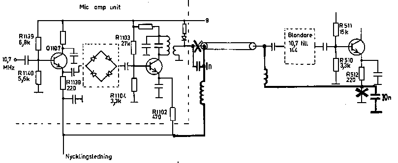
The Swedish PTS regulations require from a transmitter that the bandwidth is not larger than necessary. At telegraphy the make and break of keying have to be well rounded. Many commercial rigs do not fulfil this requirement. This article describes why one gets key clicks and how one can remove them. As far as we know, not any commercial 2m transceiver has perfect cw keying. The perfect keying is without clicks more than a few kHz away, and allow keying at 1000 lpm, to be used at meteor scatter. Key down/up ratio is also sufficient. Click free keying is easy to obtain, even if the manufacturers often not take care of it. A little bit harder is to make click free high speed keying, especially with good key up/down ratio. Yaesu FT 221 as an exampleWith FT221 as an example we will here show how one can obtain perfect keying. We hope that the text is enough detailed to allow similar modifications also on other stations.In FT221 the keying is made in the emitters of two transistors, Q1107 and Q1101, both operating at 10.7 MHz. At key up the signal is some 55 to 65 dB weaker than at key down. At dx it is more than sufficient, but locally it may make the signal hard to copy. Another 25 dB is achieved by keying one additional stage, Q503 operating at 144 MHz. The relevant parts of the schematics are shown in fig 1. In fig 1 is shown what is done to get emitter keying in Q503. All connectors on the exciter board are occupied. Because of that we chose to let the keying use same cable as the 10.7 Mhz signal, that call for 2 chokes and 2 capacitors. |

|
|
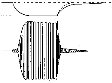
Fig 1. From the figure it is clear how the FT221 is keyed. Modifications, the bolder lines, refer to keying of yet another stage, see text. "Nycklingsledning" is key line. "Blandare" is mixer. To make the keying fast and yet without clicks requires that all the keyed stages block at about the same voltage. As the manufacturer doesn’t have such concerns, the interested ham has to solve such details himself. The different stages have to be keyed simultaneouslyThe keying in older models of the FT221 totally lacks key filtering. With addition of filter according to fig 3 one gets a result like fig 2. On the upper trace we see is the voltage on the keying line, on the lower we see that the RF voltage comes in two steps, which lead to unnecessary large bandwidth or limited keying speed. The reason is not hard to understand: The two keyed transistors Q1107 and Q1102 start to amplify when their emitter voltages are about 0.6 V below their base voltages. As one can understand from fig 1 Q1107 start to operate with about 3V on the keying line but Q1101 don't operate until 0.7 V is reached.More modern versions of FT221 are better in this concern. The bias network is altered, with R1103 as 6.8k and R1102 as 1k. With these values Q1101 will operate at 2V on the keying line. Furthermore, an unintended change is made on modern stations. The print on the circuit board for R1139 and R1140 is switched, making the resistors wrongly mounted. It does however not make any difference, since the values are about the same. But one has to check carefully when changing. The resistor from Q1107 base to +8V should be altered to 12k, and it can be labelled as ether R1139 or R1140 on the board. |
|
|
Fig 2. Different characteristic of the keyed stages will give dual time constants. The upper trace shows the voltage on the keying line. Below is the RF signal to the antenna. With a filter according to fig 4 one gets a break like the dotted line, which removes the tail of the RF signal. |

|
|
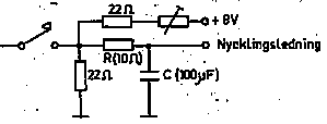
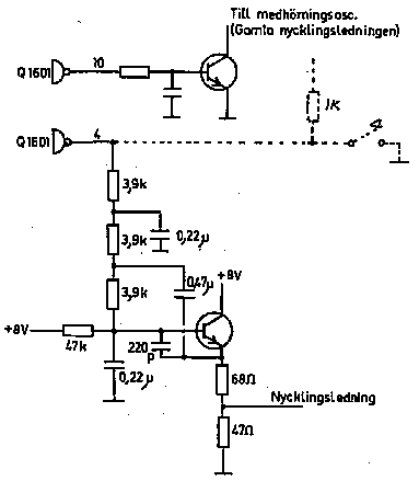
Fig 3. Simplest possible keying filter. The rise and fall times are very different, though. The keyed circuits are evaluated step by stepWhen one are going to modify a transmitter to make all stages operate at same voltage on the keying line, one should operate one stage at time while the others are grounded i.e. key down. In the momentarily keyed stage, the key is replaced by a 1k potentiometer between plus and ground.While alter and measure the voltage to the keyed stage and observe the output power, maybe by listening to the transmitter, you get an idea about the keying characteristic for each individual stage. What you want to do is to make the stages operate at the same voltage, maybe 2V. That is achieved either by adjustment of the base bias, or by applying the keying voltage trough a voltage divider. Refer to the FT225 article where the field effect transistor is keyed by a voltage divider by 6.8k to the key and 1.8k to ground. If the base voltage is changed, also the emitter resistor should be changed to keep the current at the original level. When all stages have reasonably matched keying characteristics, the only thing left is to design a circuit that steer the keying voltage with appropriate filtering. Three kinds of keying filtersThe simplest kind of filter (fig 3) have the drawback, that the break is more or less stretched, see fig 2. The shape of the make is determined by the RC link. The break depends on C and the current from the emitters’ trough the keying line.If any of the stages are keyed trough a voltage divider, also a pull-up resistor is needed (1k in FT 225) to achieve appropriate key up attenuation, as the voltage divider is parallel to the key. If keying according to fig 3 is giving too different rise and fall times, you can instead use a circuit according to fig 4. The adjustable resistor is set to barely choke the transmitter with the key up. In this circuit the low ohmic voltage divider will cause the break to be about as fast as the make. For regular CW a keying circuit according to fig 3 or fig 4 is good enough. If one wants to key in high speed, a more elaborate keying circuit is needed though. The idea is that a multipole active low pass filter feeds the keying line with low impedance, thus the key line current is without influence. According to fig 5, with R = 3.9 k and C = 0.22 µF, one can key up to 1000 lpm speed. The smaller of R2 or R3 should be a lot smaller than R, maybe 1k. The key up voltage is adjusted with R2 and R3 to barely choke the transmitter. The output power can be adjusted with R1, and should be adjusted so that any ALC circuits are not activated. In many stations, as in FT221, there isn't any negative voltage accessible. With the modifications in this article a filter according to fig 6 is working excellent. The key shape circuit Q1601 is not necessary any more, but as it already is there it can remain. In older stations, that don't have the Q1601 board, a resistor (dashed in fig 6) can be used as well. In that case the side tone is put directly to the key. The 47 k resistor in fig 6 has the same function as R1 in fig 5. The active low pass filter with an emitter follower requires that the voltage on the base never falls below about 0.8 V. Thus that resistor should not be larger than 47 k. The voltage divider 68 and 47 ohm have the same function as R2 and R3 in fig 5. The 220 pF capacitor is necessary to prevent rf rectification in the transistor. |
|
|
Fig 4. With this filter one achieve almost identical rise and fall times. |

|
|
Fig 5. With an active filter according to this one achieve high keying rates without key clicks. Rut i.e. Rout shall be low enough that the emitter follower always have current. |
|
|
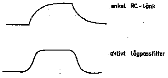
Fig 6. If no negative voltage is accessible a circuit according to this can be used. It is designed for FT221, but can with small changes of resistor values, see text, be used in other stations. The Q7601 is omitted and the key is connected according to the dashed lines. "Medhörning" is side tone. Morse keying, a kind of AMThe difference between a keying according to fig 3 or 4 and fig 5 or 6 is seen in fig 7. As you see, morse keying is a kind of amplitude modulation with square wave.With a simple rc-link the sidebands = key clicks decreases by 6 dB when the frequency difference is doubled. With the active filter they decreases instead by 18 dB, resulting in that both faster keying and less key clicks are possible. |
|
|
Fig 7. The envelope of the keyed signal when the filter is a simple RC-link and when it is an active filter. To SM 5 BSZ Main Page |