Losses in yagi antenna elements at 144 MHz
When simulating yagi antennas with NEC2, NEC4 or OMNEC one typically uses the bulk conductivity of the element material as one of the input parameters to the simulation program. This is well justified for new (uncorroded) elements that are mounted on a non-conducting boom tube but it is not self-evident that a real antenna that has been used for several years will have as small losses as predicted by the simulations.There are several mechanisms by which element losses may increase above the values computed by the modelling software.
-
Reduced surface conductivity due to corrosion.
-
Ohmic losses due to Eddy currents in the boom tube or other
conducting materials near the element center.
-
Magnetic losses in washers, screws and other magnetic materials
near the element center.
-
Dielectric losses in surface coatings used to prevent corrosion.
- Dielectric losses in plastic plugs at the element tips.
At VHF frequencies element losses are much less important than they are at UHF frequencies because system noise temperatures are not much lower than the environmental temperature and therefore element losses only affect antenna gain, not the system noise temperature for the receiver even when the antenna points into cold sky.
Measured Q-values in a cavity
This study is less accurate than our similar study on 413 MHz but the results are accurate enough at the present time to allow us to choose surface treatment and mounting methods for our 144 MHz antennas.Aluminium rods and tubes with various surface treatments or mounted on short segments of boom tubes as well as a copper rod were placed in a box with dimensions 1.2m x 0.9m x 0.9m, see figure 1. The box with a yagi antenna element inside consitutes a coaxial resonator to which a network analyzer was loosely coupled with capacitive probes. The coupling was weak and the losses through the box was 40 dB or more at the peak of resonance.
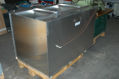
Fig 1. The box in which element Q-values were measured. |
|
Table 1 shows Q-values observed for different surfaces. The accuracy of the data in table 1 is limited because the elements were not cut to the same frequency, something which is approximately corrected for in the table. The data allows the conclusion that protecting the surface by anodizing is perfectly OK while with powder coating (100u powder coating, polyester, Interpon 610 from Akso Nobel, product code MW701D Silver, RAL9007) is not a very good idea for yagi antennas but that it would be fine for stacked dipoles that have. The ratio of Q-values between copper and aluminium is 1.204 while the ratio of the square root of resistivities is 1.364, a reflection of the fact that elements with higher Q-values are more affected by the losses of the box. |
                Q-value for element inside box.
Coating       diam=10mm     diam=6mm     diam=4mm
 None           6420          4275        3180
Oxide 15u       6340          4260        3120
Oxide 30u       6230          4150        3030
Paint 100u      5680          3540        2600
Copper          7730          ----        ----
Table 1. Q-values inside box for different coatings on aluminium and for copper. The frequencies are between 140 and 153 MHz but the frequency differences are accounted for in an approximate way |
|
Elements anodized to an oxide thickness of 30u have a Q-value that is about 97% of the Q of the pure metal. The box will affect the anodized elements less because of their slightly lower Q so it is reasonable to assume that anodizing to 30u causes a loss of 4% on 144MHz. Anodizing to 15u should cause losses of about 2%. |
                                   Q-value for element inside box.
Mounting                              diam=10mm     diam=6mm     diam=4mm
 None                                   6420          4275        3180
Isolator+screw,no boom                  6230          4160        ----
Isolator+screw,boom diam 31mm           6180          4020        ----
Isolated through 31mm boom. Glued.      5830          ----        ----
Isolated through 31mm boom. Starlock.   4440          ----        ----
Isolated through 20mm boom. Glued.      ----          ----        3075
Isolated through 20mm boom. Starlock.   ----          ----        2520
Starlock washers only. No boom.         4650          ----        2625
Table 2. Q-values inside box for aluminium elements mounted on boom tubes. The frequency is 144 MHz. |
|
Elements mounted on top of a 31 mm boom tube at a distance of 9 mm with a nylon isolator as shown in figure 2 have a Q-value that is approximately 95% of the Q-value of the element alone. The losses of the box affect elements with higher Q more than elements with lower Q so when taking that effect into account it is reasonable to assume that this mounting method increases the losses by 7%. |
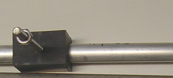
Fig 2. Element with nylon insulator for mounting 9 mm above boom. |
|
Elements mounted isolated through holes in the boom tube have slightly larger losses than elements mounted above the boom tube and Starlock Washers have rather high losses, most probably because they are ferromagnetic. For isolated elements mounted through a boom tube with Starlock washers the Q-value is about 75% of the Q-value of the element alone. Taking the effect of the box into account might change this value to typically 65%. The investigation presented on this page allows the following conclusions for the design of antennas at 144 MHz:
|