Note that the information on this page is only applicable when
16 bit MMX instructions are selected for the first backward FFT
and/or the second FFT. If your computer has CPU power for the 3 times slower
float algorithms, use float and do not worry about the information on this page.
Skip many words and go to the practical
procedure of setting up linrad correctly
Maximum number of bits in the input signal
At the present time (year 2001) the standard audio board
samples 16 bit at 44.1 or 48kHz.
There are boards that are sold as 24 bit 96kHz but as often
in the HIFI industry, hardware is overspecified.
When actually sampling at 96kHz the number of bits is much
lower than 24.
The 24 bit board will give perhaps 10dB more dynamic range,
not 48 dB as one would expect from 8 more bits.
The maximum S/N for an A/D converter is 20 * log(N) + 10 * log(12)
which evaluates to 107.1dB for a 16 bit A/D converter with N=65536.
When sampling at 44.1kHz, the bandwidth is 22.05kHz so the noise floor
due to quantisation noise is at -150dBc/Hz.
(dB below a near saturating carrier in 1Hz bandwidth)
This formula implies that the noise floor due to
quantisation noise is 0.29 bit RMS
In real life quantisation noise is eliminated by allowing
some extra smaller bits that sample essentially amplifier
and thermal noise.
As a consequence the noise floor is normally something like 20dB
above the quantisation noise limit.
This means that the degradation when loosing one or a few
bits is very small - the smallest bits contain mainly noise.
This is no critisism at all. To make the quantisation noise
contribute to the total noise by 1% only, the noise floor
has to be placed 20dB above the quantisation noise.
Experimentally, a 16 bit soundblaster PCI gives a S/N of
about 115dB at 25Hz bandwidth or 139dBc/Hz as measured by linrad.
This is 11dB above the quantisation noise limit.
If two bits are cleared before the signal is further processed,
performance is degraded by 4dB, the noise floor is at
135dBc/Hz while the quantisation noise limit is at 138dBc/Hz.
Removing 3 bits from the degrades the measured value to 130dBc/Hz.
When 3 bits are removed, practically only quantisation noise
is determining the noise floor.
The discrepancy with the theoretical value, 2dB is because the bandwidth
in linrad is not quite the noise bandwidth, it is a bandwidth calculated
from 1/time for the 6dB points of the fft window function.
Dynamic range values measured by linrad are always underestimated
by 2dB throughout this site SM5BSZ / Linrad Home Page
A modified Delta44 soundboard gives a dynamic range of 146dBc/Hz
when sampling at 96kHz.
When talking about number of bits it may be reasonable to compare
to a A/D converter having the quantisation noise at 168dBc/Hz, 20dB
below the actual noise floor, taking the 2dB bandwidth error of
linrad into account.
Sampling at 96kHz means a bandwidth of 48kHz so the maximum S/N
in full bandwidth is 121dB.
According to the formula above we have:
16 bit 107.1dB
17 bit 113.1dB
18 bit 119.1dB
19 bit 125.1dB
The modified Delta44 can be characterised as a 18 bit A/D converter with
the noise floor 18dB above the quantisation noise.
In its original shape the Delta44 can be characterised as a 18 bit
unit with the noise floor 21dB above the quantisation noise.
When the Delta44 is run in 16 bit mode, the quantisation noise is
increased by 12dB.
The other contributions to the noise floor are 6 dB higher for the
modified board so running the Delta44 in 16 bit mode leads to a loss
of 1 dB only.
In its original shape the loss from running the Delta44 as a 16
bit converter is only 0.5dB!
Based on the performance of currently available A/D converters
it seems reasonable to design linrad for 19 bits of valid input
data.
Dynamic range of the output from the first fft
When running linrad at wide bandwidths the first fft is used only
to separate out very strong signals so the noise blanker can operate
properly.
For this purpose there is no reason an fft with much narrower bandwidth
than the strong signal.
This means that the size of the first fft is typically 4096 (N=12) when
linrad is run at maximum bandwidth.
Assuming that 19 data bits of the input is more or less valid
a near saturating signal will need 31 bits after the 12
butterfly loops that each multiplies the level by two.
The noise floor from the A/D converter which is represented by
2 bits will grow by the square root of two for each loop
since the two voltages added are uncorrellated.
The noise floor is therefore represented by a number corresponding
to 8 bits.
The first fft of linrad is performed with floating point numbers.
They use 23 bit for the mantissa so worst case rounding errors
are 8 bits.
This is an error in the strongest signal and it is
completely insignificant.
The rounding errors of the previous fft loop will go into the noise floor
at some frequency where there should be no contribution at all from
the strong signal.
Two large numbers, both with 7 bit rounding
errors are combined and they produce a noise contribution at one frequency
that is 3dB below the A/D noise floor.
The 4 byte floating point arithmetics is enough to preserve the
dynamic range of a 19 bit A/D converter with a noise floor that
is 12dB below the noise of a modified Delta44.
The strongest signal may be 23 bits above the noise floor and the
noise floor has to be represented by 2 to 3 bits to avoid introduction
of quantisation noise so the fft1 output needs 26 bits when represented
as integer numbers.
In order to allow the fft1 back transformation with MMX instructions
it is necessary to separate out all frequencies that need more
than 16 bits.
The time function that results from the fft1 back transformation
will be used as input to the second fft which may be several
times larger.
If fft2 is selected to be 65536 (N=16) it is necessary to limit
the strongest frequency in the fft1 output to 12 bits only
since an owerflow could otherwise occur in the second fft.
The zero point of the main fft display
Since the first fft is calculated with floating point numbers it
does not matter where the zero point is placed for the transform itself
or its display.
If the second fft is disabled you can shift the spectrum up and down
the dB scale by use of the parameter First FFT amplitude which
is 2000 by default.
You will have to adjust the output audio volume accordingly but
processing is not affected.
When the second fft is enabled, the output of the first fft is
rounded to integer values and it is essential that the white noise
floor is placed high enough above the quantisation noise caused
by loosing the floating point decimals.
For the noise blanker to operate it is essential that the noise
floor is placed low enough.
More about that below.
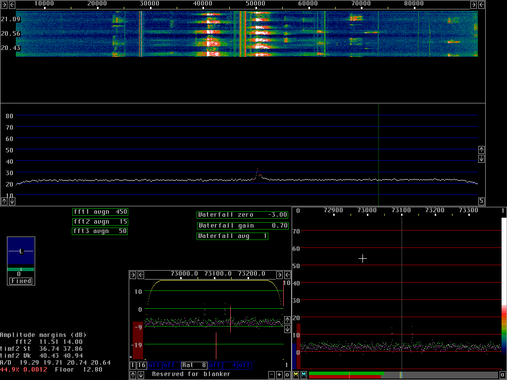
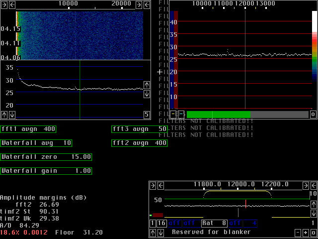
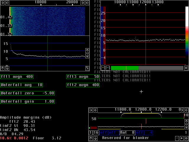
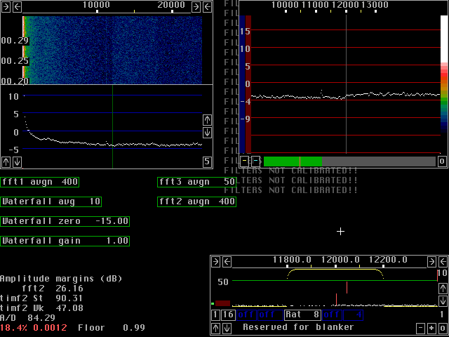
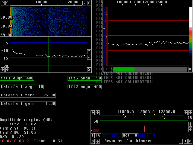
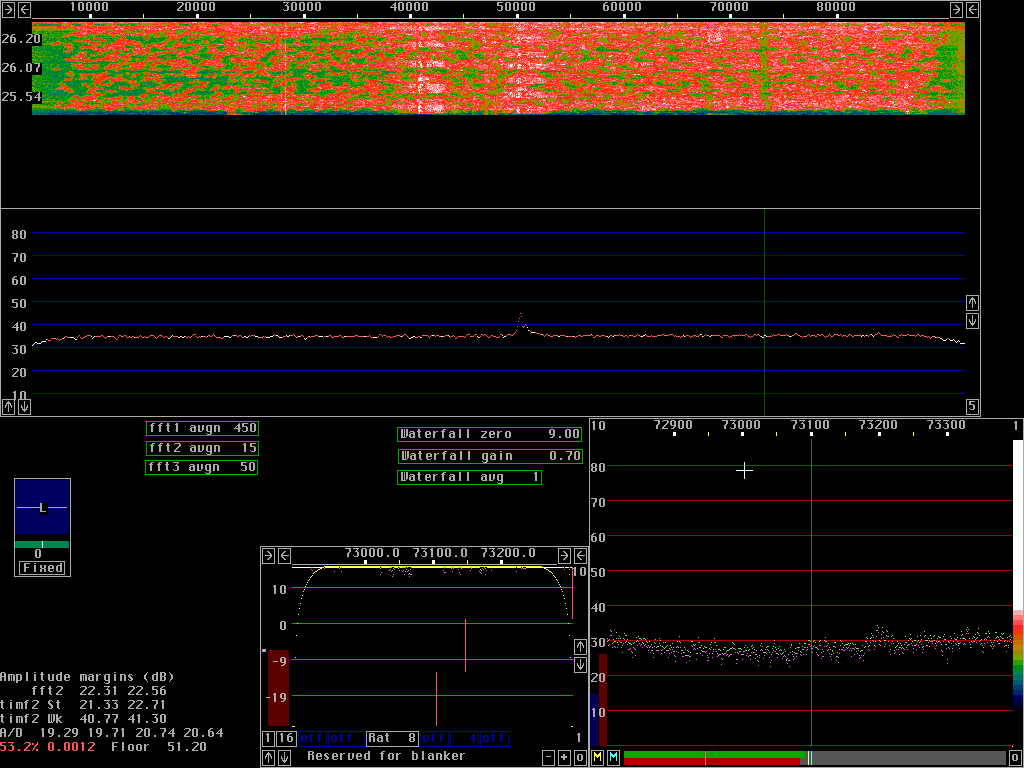
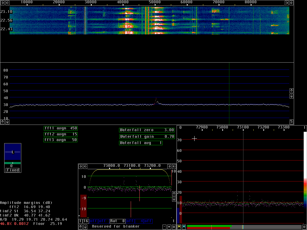
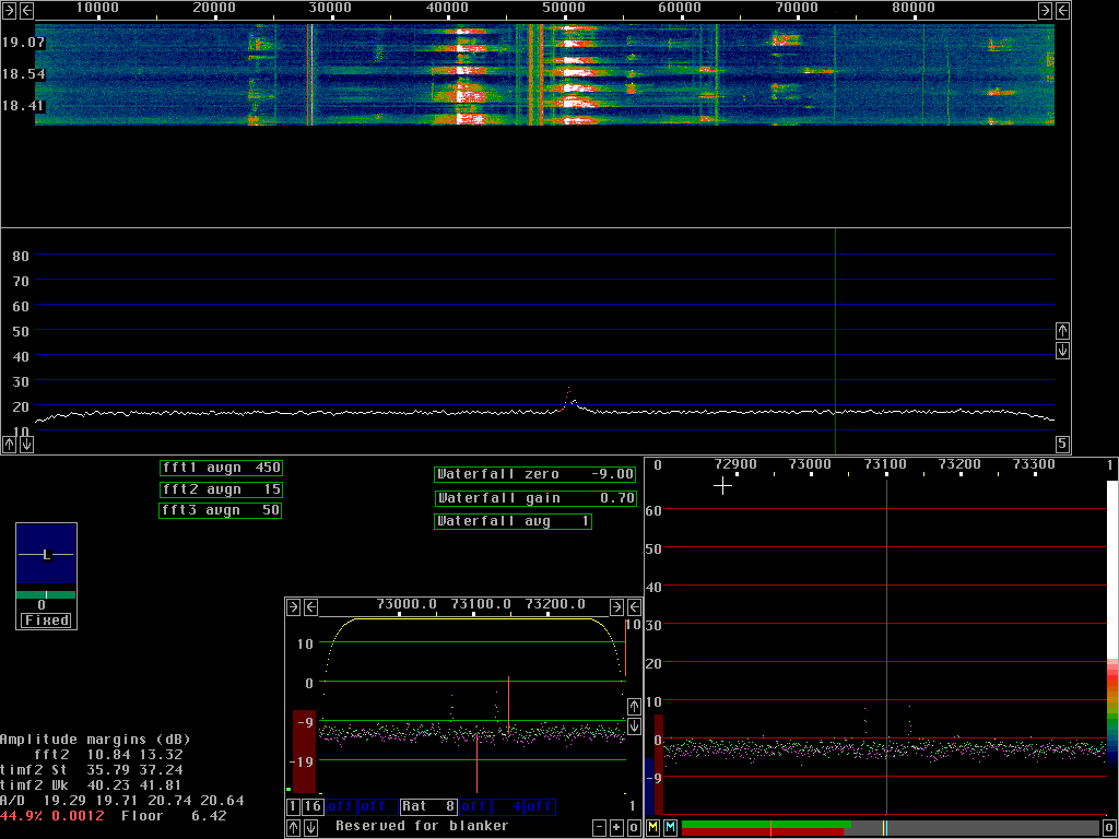
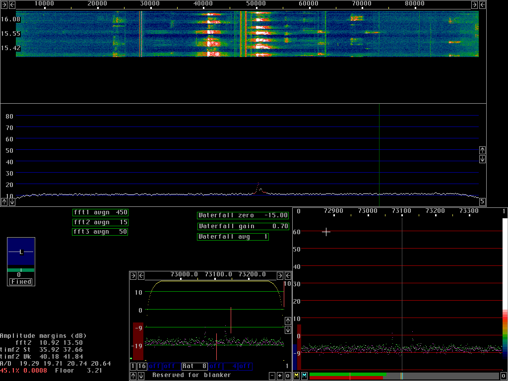
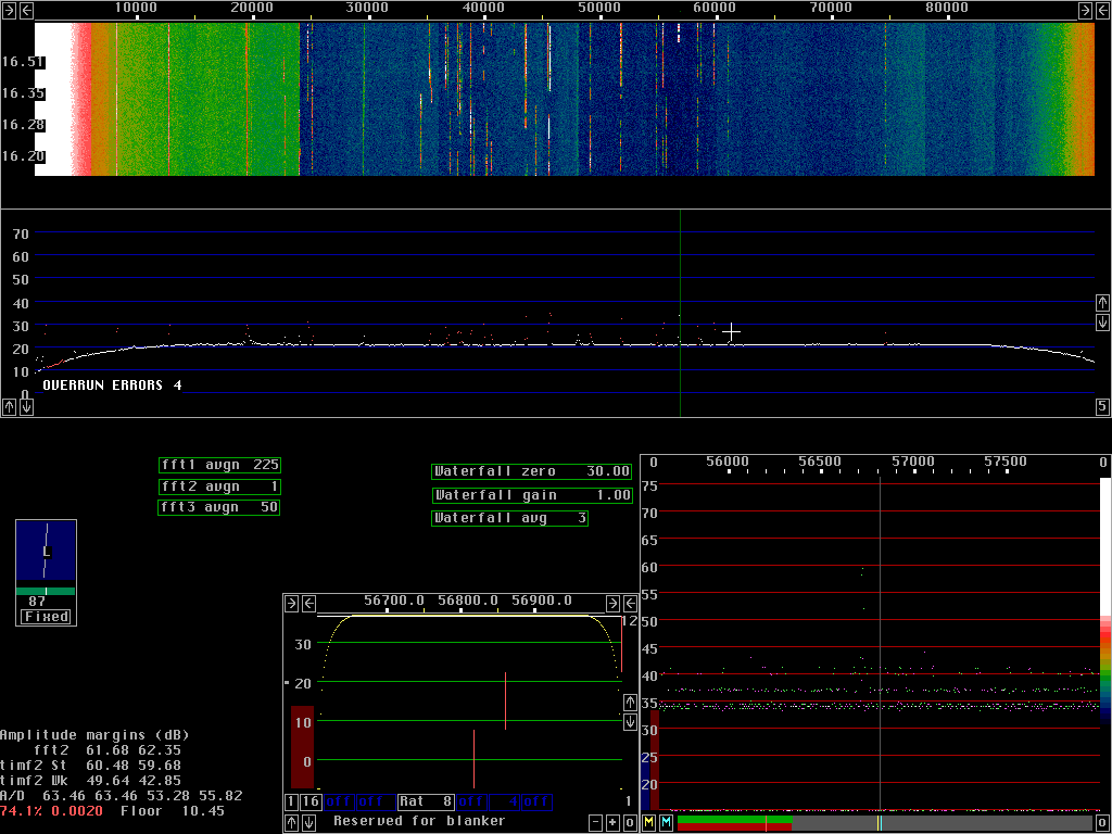
Compare the figures 1 to 5.
These figures are produced from exactly the same input
from the A/D converter (stored on the hard disk).
A weak tone at 11.2kHz is injected into a Delta44 sampling
at 96kHz.
The size is 2048 for both fft1 and fft2 with sine to power 4 windows
for both.
The x-axis is one pixel per bin for both fft1 and fft2.
Note that the second fft gain parameters have to be adjusted to keep
the processing within 16 bit to avoid introduction of other
rounding errors (more about them further down this page).
To set First FFT amplitude, first press A to get the amplitude
information in the lower left corner.
The bottom line gives the noise floor in bits RMS.
If you have a nice location with a noise floor that is essentially
white noise of constant amplitude, you should find the noise floor
somewhere between 10 and 30 dB when using the default parameter
value 2000.
The Floor RMS value should be in the range 3 to 30.
The soundboard itself should be somewhere
between -5 and +5dB and your analog hardware should add
between 15 and 25 dB.
In most situations there is no reason to do anything, just use
the default value of 2000.
In case your hardware is not properly adjusted you should change
the First FFT amplitude parameter to place your white noise
background somewhere in the 10 to 30 dB range..
| 