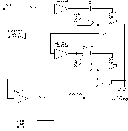
A simple X-tal filter
Old-fashioned 100 kHz calibrator crystals have extremely high Q. By using them in a quite conventional crystal filter, very narrow bandwidths can be obtained.With the arrangement I use, as shown in the diagram below, the bandwidth can be varied continuously from 2 Hz up to 2 kHz by turning a pot. The signal level remains constant for all bandwidths.
This filter is designed to recover weak CW signals in white noise. Therefore the shape factor is poor. In my experience, a filter with flat passband and steep sides will perform less well for this purpose, but of course, if you need a filter to select one CW station in a HF pile-up this is not the design to choose.
Commercial filters are usually designed for the more difficult task to dig out one weak signal that is surrounded by much stronger signals. Therefore it may be difficult to buy a filter that is really good for weak signal work on VHF.
Fortunately, the filter that is optimal for weak signal reception is easy to build - and of course many other designs than the one described below will produce a similar frequency and phase response.
If you feel uncertain whether a filter with this kind of characteristics would be beneficial to you, look and listen here demonstration with audio and spectrograms how a weak EME signal sounds with different kinds of filtering.

This filter is composed of two identical filter sections connected in series with an isolating amplifier in between. Each of these filters is of the basic one X-tal design used in world war 2 military receivers.
How to use the filter - and tune it.
The RX signal is taken out at the IF, and for weak signal work, no AGC is used. When using a narrow filter, AGC derived from the full IF passband may cause problems - and AGC derived from the output of the narrow filter is not meaningful. To protect your ears, use an amplitude limiter on the audio. I use an op-amp with a 300 ohm resistor in series. The op-amp can deliver no more than +/- 10 volts, so the sound level becomes limited to a level that suits me.The oscillator at 10.6 MHz has a readout that can resolve 1 Hz, and it is calibrated in a scale that is identical to the scale on my spectrum analyser. The spectrum analyser operates similarly to FFTDSP by AF9Y. It is very difficult to use narrow filters if you do not have an averaging FFT spectrum analyser. But if you have one - it is not difficult to find and tune correctly to very weak stations.
The signal output from the mixer goes through the crystal X1 to a resonant circuit L2, C2. L2 is large, so C2 is only the stray capacitances plus a 50 pF trimmer. In this way the impedance is very high, maybe 10 megohms, at the warm end of L2, C2 when the bandwidth control is set for maximum, 50k ohms.
By turning the bandwidth control, L2 can be loaded. This leads to a reduction of the bandwidth. When L2 is loaded down to the point where the impedance at the warm end of L2, C2 equals the series resistance of the crystal at resonance, half the voltage is across the crystal, and half the voltage is over L2, C2. If the buffer amplifier can take the load without any loss of output voltage, this will be the point when attenuation through the filter is 6 dB. The bandwidth is then around 1 Hz. Reducing the load on L2 will quickly reduce the filter losses while the bandwidth gradually increases to a few kHz. In this context, low output impedance means 500 ohms or so.
C1 and C2 are tuned for a symmetric frequency response with L2 unloaded. If the Q and L/C ratio of L2 is properly selected, a flat response with SSB bandwidth is obtained. (This tuning has little effect at narrow bandwidths) C1 is tuned for symmetric sides, far outside the 3 dB points, while C2 is tuned for a flat pass band.
L1 serves to produce an 180 degree phase shift to use for the balancing by C1 of the crystal parallel capacitance. If you prefer, this phase inversion can be done with silicon. You may also tune L1 with a capacitor, but then a large C and small L1 will be necessary for L1 and its additional capacitor to load the output of the amplifier a few kHz off resonance. If the 10.7 MHz signal already passed a SSB bandwidth filter, tuning of L1 will not give any advantage.
The second filter is identical. The capacitor C3, connected in series with X2, should be connected in series with X1 or X2. It will rise the frequency of the crystal to which it is connected slightly, and it is needed to make the two filters operate on exactly the same frequency when they are both in the narrowest mode.
Finally the signal at 100 kHz is mixed down to audio with a BFO. It is nice to be able to vary the tone. With 20 Hz bandwidth, the white noise sounds much like a tone, and it seems to be efficient to place the passband at a low audio frequency to best copy very weak signals. If the bandwidth is set higher, (high speed CW), also the tone should be set higher for best performance.