SM 5 BSZ - Dynamic Range of 2 m Transceivers Part 4: Modifications to the FT 221
Published in VHF communications Nr 2 1982.
Deutsch
Svenska
A comparism of values measured on wellknown commercial 2 m transceivers was given in part 1 (VHF COMMUNICATIONS 1/82) of this series of articles. Part 2, also in edition 1/82, gave a number of modifications to the TS 700, where part 3 (edition 2/82) gave modifications to the IC211 and IC245. The following part 4 will show how the FT 221 can be improved with respect to its dynamic range.
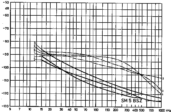
With respect to its noise sidebands, the FT 221 is one of the better stations even before modification. However, a few additional modifications can improve it considerably. The three stations given in Figure 1 were used for experiments and lead to the described modifications.
Both the FT 221 and FT 225 can be equipped with a high-performance front-end board manufactured in the UK by Mutek. However, the high dynamic range of the Mutek board can only be utilized to the full if the VCO is modified.
Mutek specifies that an interfering signal at 144.300 MHz can be 115 dB over noise before an S9 sianal at 144.400 MHz is dearaded by 3 dB due to desensitization. This specification is hardly of interest, since a weak signal will be well in the noise due to the unwanted conversion with the noise sidebands of the VCO.
In its original state, the noise sidebands of the VCO are at - 90 dB. With an input signal of 115 dB above noise, the effective noise figure will be increased by 25 dB. This means that the same performance of adding the Mutek frontend could be obtained by inserting a 20 dB attenuator between antenna and receiver !
The two-tone dynamic range is more important (see the previous article). This is usually dependent on the purity of the local oscillator signal, or on the large-signal characteristics of the front-end. Little is achieved by improving the wrong circuit.
The situation is quite different when the VCO is modified. In this case the VCO noise can be reduced by appromiately 20 dB at a spacing of 100 kHz which should directly improve the transmitter correspondingly (although the improvement is less in some cases as can be seen below). A Mutek or similar front-end will be required in addition in order to obtain a large improvement on the receiver.

Fig. 1: Sideband noise as a function of frequency
spacing from carrier Source: Three original FT 221
(dash/doned lines), and after various modifications

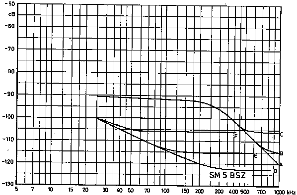
Fig. 2: The effects of a good input circuit and improved vco
The FT 221 annotated "1" in Figure 1 was measured in the receive mode. Curves A to C in Figure 2 are those measured with the original VCO: whereas D to F show the results after the VCO modifications described in this article. Curves B and E were measured with the original front-end having a noise figure of 8 dB, which is typical for a Japanese transceiver. It would not be fair to make a direct comparison to such a transceiver equipped with a Mutek front-end having a noise figure of less than 2 dB (see curves A and D).
If a good preamplifier having a gain of about 15 dB is added to the original front-end, this will provide a performance similar to curves C and F. In this case, the noise figure would be the same as with the Mutek front-end, and a direct comparison between curves D and F shows the improvement that can be obtained by replacing the front-end in a station where the VCO has been modified.
A direct comparison between curves A and C shows that no improvement is obtained at moderate frequency spacings when using the original VCO, which underlines the above considerations.
In the case of the FT 221, the noise sidebands are mainly caused
by noise from the phase comparator (Note the unusually flat noise
spectra of unmodified stations).
This noise can be suppressed by changing the value of R 302
from 2.2 kiloohms to 100ohms, and C 301 from 0.1 microfarad to 2.2
microfarad (see Figure 3).

Fig.3: Circuit extract with details about parts to be modified
After carrying out this modification, performance is improved at frequency spacings in excess of 50 kHz, whereas the noise increases at lower frequency spacings. The source of sideband noise at this stage is the same as with unmodified IC 211 and IC 245 transceivers (see previous article in this series). The original fast response of the phase-locked loop in the FT221 allowed the phase modulation of the VCO itself to be suppressed, however, this is no longer possible after changing the values of R 302 and C 301. This explains the degraded performance adjacent to the required frequency.
In order to obtain the performance shown in Figure 1, it is necessary to suppress the effects of the leakage currents by replacing R323 and R 301 by RF-chokes. This was discussed in conjunction with the IC 211/lC 245. It is also necessary to suppress noise from the varicap diode D 306 of the bandswitch. This is achieved by cutting the conductor lane between R332 and C338 and bridging it with a 100 kQ resistor. It should be noted that the original circuit diagram is not correct (for corrections see Fig.3). The 100 kiloohm resistor and C 338 then form a low-pass filter. Also C338 represents a low-impedance path for the noise components of the leakage current through the varicap diode. It should be mentioned that R 301 is usually replaced by an RF-choke in the factory.
The above changes cause the locking-in process to be 20 times slower. It is therefore necessary to change the value of C 342 from 0.1 microfaraduF to 0.68 microfarad. Capacitor C 342 is in the circuit that detects an unlocked condition. It is necessary to increase the time constant, otherwise the transmitter could be switched on with the oscillator in unlocked condition.
One of the stations did not work after carrying out the above modifications. The reason for this was that the saw-tooth generator comprising C 301, R302, R306, and D301 (unijunction transistor) no longer oscillated. The unijunction transistor was conducting continuously, with approximately 1 V at base 2 (connected to C 301). This problem was solved by increasing the emitter current by changing the value of C 303 from 10 microfarad to 100 microfarad and R 304 from 200 ohms to 100 ohms. Replacing D 301 or inserting a resistor in the base 1 line, possibly in parallel with a large capacitor, are maybe a safer alternative.
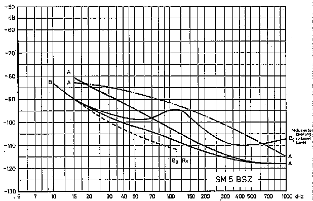
Several FT 221 transceivers have been modified as above. The results shown in Figure 1 are representative, however, one source of sideband noise has still not been detected. It can be seen in station 3 of Figure 1, and the worst case known to the author is shown Fig.4, station A. This station was measured and modified at the 1981 +nnaboda meeting. Unfortunately there was no time to investigate the problem.
Noise sidebands can be generated by amplitude modulation as a result of an insufficiently decoupled supply voltage to any ampli fier or mixer in the transceiver.
A good example of this phenomenon is both the TS 700 described in the previous article, and station B given in Figure 4, which was modified according to a description where a potentiometer was connected in series with the emitter resistor R 512 of an amplifier to allow adjustment of the power output. Noise sidebands increase considerably when the power is decreased in this manner. The additional noise is probably caused by an increased sensitivity to AM of Q503 as the current through this decreased. This can be suppressed by decoupling the supply voltage using a capacitor having a few microfarads. Station B was measured in +nnaboda, however, before the problems could be studied in detail the station became defective due to a short-circuit that destroyed one of the driver transistors. The author still does not know whether the noise sidebands can be reduced at full power by providing an adequate decoupling of the supply voltage.
When comparing the receiver performance of station B of Fig. 4, there is sure to be some AM noise in the transmitter even at full power output. This appears as additional noise at frequency spacings of approximately 100 kHz.
The time constant of the locking-in process is increased after carrying out the previous modifications, which is a disadvantage when using split-frequencies (FM-repeaters). This effect could be avoided using a few extra compo- nents (see previous article on IC 211/lC 245). However, since this effect was not considered to be important, no further experiments were made.
The keying of the FT 221 is very unsatisfactory as with most Japanese transceivers. Keying produces strong key-clicks. Despite this, the keying of many transmitters is not fast enough for high-speed meteor scatter work due to the poor design of the keying system.
A further article is to show how it is possible to get perfect keying without back-lash up to l0OO letters per minute, and with no key-clicks at a separation of 3 kHz. Both the principles and practical installation into the FT 221 are to be described.

Fig. 4: A very poor example with unwanted AM due to poor bypassing,
as well as effects caused by the emitter potentiometer used for
output power reduction