SM 5 BSZ - Dynamic Range of 2 m Transceivers Part 1: Introduction
Published in VHF communications Nr 1 1982.Deutsch
The satisfaction of DX communications on the 144 MHz band is often spoiled nowadays due to interference from neighbouring stations. The cause is usually an inadequate dynamic range of transmitters and receivers ! The greatest problems with modern equipment are caused by the noise sidebands of the local oscillators. They decrease the dynamic range in both receivers and transmitters; often to a very great extent. These problems were discussed in an article published by DJ7VY (1), which also included a description of a good, clean VFO.
The following article represents an introduction into a series of articles in which simple modifications are to be described for popular 144 MHz transceivers available on the market. These modifications will result in a considerable improvement of their dynamic range.
Basic Considerations
Table 1 gives three typical situations to indicate how high the dynamic range, and how low the noise sidebands must be if 2 stations are to operate simultaneously. The worst case is assumed where the two antennas are pointing directly to another.
Output    Antenna    Distance   Dynamic      Noise side
power    (Element/     (km)      range      band suppres-
 (W)       gain)              (BW = 3 kHz)   sion (dB/Hz)

300      40/17.5 dBD    2        149dB         -184
 50       10/11 dBD     5        120dB         -155
 10     Halo/- 1 dBD    5         89dB         -124
Table 1: Required dynamic range and noise sideband suppressions for three typical situations
The values given in Table 1 show us that a very large dynamic range is very useful, and the characteristics of the equipment should be optimised as much as possible within reasonable cost limits. The situation with modern equipment is usually opposite and the dynamic range is usually limited by lack of care during the design of the circuit.
In this article, and the following descriptions, the dynamic range will always be referred to a SSB bandwidth of approximately 3 kHz, i.e. the values in Table 1, fourth column, can be directly compared to the diagrams. The importance of the numerical values can be easily understood in the case of the transmit spectrum; however, in the case of the receivers we differentiate between the two-tone dynamic range, and the three-tone dynamic range.
The two-tone dynamic range is measured as the level of an interfering signal that reduces the signal-to-noise ratio of a required weak signal by 3 dB. In this case, the interference signal level is measured in dB over the noise floor (at a bandwidth of 3 kHz). In modern receivers, the two-tone dynamic range is usually limited by the noise sidebands of the local oscillator. It can, however, be determined by the overload characteristics of any amplifier or mixer, and will, in this case, be in the vicinity of the 1 dB compression point (in dB over the noise floor).
The three-tone dynamic range - or intermodulation-free dynamic range - is related to the third-order intercept point, and is measured as the level (in dB above the noise floor) of one of two equally strong signals that produce intermodulation products of the same level as the noise floor.
In the above discussion, all signals are assumed to be within the 144 MHz band. Image-frequency response, second-order intermodulation (e.g. 48 MHz TV-signals plus 96 MHz FM carriers), and other problems caused by out-of-band signals, are not to be discussed here, since they can be easily suppressed using suitable filters.
The two-tone dynamic range may be very low at certain frequencies due to spurious reception points, however, this is a minor problem that is not usually present in modern 144 MHz transceivers, and is therefore not to be discussed here.
Finally, the three-tone dynamic range is not to be discussed in detail here, for the following reasons: In practice, the interference caused by intermodulation is not so severe since at least two, very strong signals must be present simultaneously; the interference caused in this manner only appears at a limited number of frequencies, which means that a skilled operator can avoid them.
A receiver having a good two-tone behaviour, will automatically possess a good three-tone range, whereas the opposite may not be true due to the noise sidebands.
The intercept point and its importance has already been discussed in detail in amateur radio publications.
Request specifications regarding the dynamic range before purchasing your next transceiver!
The aim of this series of articles is to improve the very unsatisfactory situation. This information has been partly published in the Swedish Magazine "Radio och Television". The author wishes to make radio amateurs aware of the fact that there are very great differences in the dynamic range between different transceivers. If more amateurs request dynamic range specifications, the manufacturers will be forced to put more effort into these problems if their equipment is to remain popular on the market. The manufacturer that is able to quote a transmit signal purity of -100 dB in 25 kHz spacing, and - 110 dB in 100 kHz spacing (bandwidth 3 kHz), and to quote the same numerical values for the two-tone dynamic range of the receiver, would have a considerable advantage over other manufacturers on the market.Measured values indicate the present standard of transceivers
The costs involved in achieving the previously mentioned dynamic range are negligible. This will be proved in the following articles of this series. In order to illustrate the present situation, the author would like to show the results of measurements that were mainly made at the VHF-meeting held in �nnaboda in 1981. The illustrations show the signal purity of transmitters in the CW-mode.Figures 1 to 4 show typical measured values for types FT225RD, FT221, IC211/245, and TS700 in that order, both in their original condition (upper curve), and after modification (lower curve). The modifications will be described in subsequent articles of this series.
In the case of transceivers IC260E / IC251E, the measured values spread considerably from model to model; Figure 5 shows four of these. The reason for this spread has not been examined. Furthermore, no experiments were made, to improve this type of transceiver. The run of the two upper curves already indicates a poor filtering in the phase-locked loop.
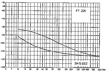
Fig. 1: Vertical scale = power difference to the main carrier;
Horizontal scale = frequency difference to the carrier.
Noise sidebands from the FT225 before (above) and after (below) modification
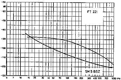
Fig. 2: As in Fig.1 - in this case for the FT221
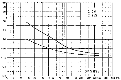
Fig. 3: As in Fig.1 - now for the IC 211/lC 245
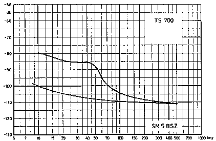
Fig. 4: As in Fig.1 - this is for the TS700 (see part 2 of this series)

Fig. 5: As in Fig.1 - measured values of 4 different IC260E / IC251E exhibit a spreading of upto20dB
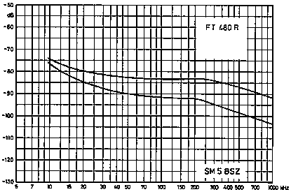
Fig. 6: As in Fig. 1 - two different transceivers type FT480 R in their original state.
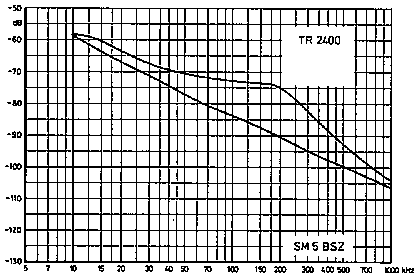
Fig. 7: AsinFig.1 - two different transceivers type TR2400 in their original state
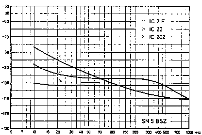
Fig. 8: The noise sidebands of many individual transceivers of types 1 (IC2E) and 3(IC202) exhibit always the same characteristics.
At 10kHz the upper curve is IC2E and the lower IC202.
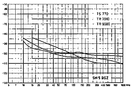
Fig. 9: The noise sidebands of 3 further types.
At 15kHz the upper curve is TS770 and the lower TR9000.
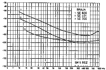
Fig. 10: Noise sidebands of 3 well-known BRAUN-transceivers At 15kHz the upper curve is SE600 and the lower SE300.
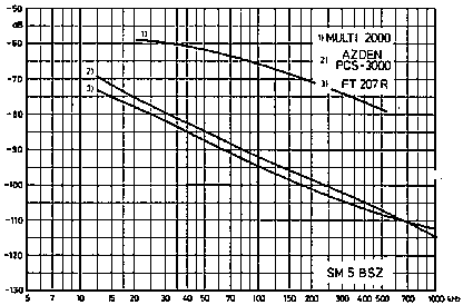
Fig. 11: The noise sidebands of type 1 (MULTI2000) are remarkably high.
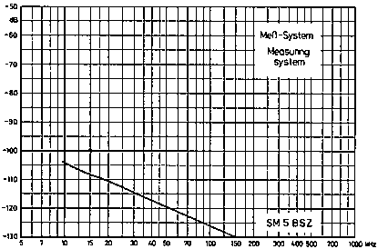
Fig. 12: An IC202 with a 144 MHz crystal filter connected to the output was used as the beatfrequency oscillator
Figure 6 shows the measured values for two different transceivers type FT480 R. In the case of these two transceivers, the noise is caused by too low a signal level at the output of the crystal filter. In principle, this should be easy to modify, but due to the compact construction, this may be difficult in practice.
Figure 7 shows measured values of two different TR2400. This transceiver is clearly poorly designed and constructed, and the manufacturer is well advised to improve this unit as soon as possible.
Typical measured curves are given in Figure 8 for transceivers type IC202 and IC2E. A large number of these transceivers were measured, and all showed values very near to these curves. Figure 8 also includes values for transceiver type IC22; however, only one unit was available for the measurement.
Figures 9, 10, and 11 are also only based on one transceiver per type. It is therefore unknown to what extent the measured values spread from unit to unit.
All measurements were carried out with a home-made transceiver having a very large dynamic range. Figure 12 shows the performance of the measuring system, that is obtained using a IC202 followed by a 144 MHz crystal filter.
In general, the two-tone dynamic range of the receivers is similar to the measured values for the purity of the transmit signal. However, measurements were only made on certain types.
Additional interference may be produced when the transmitters are modulated. Several models produce very strong key clicks, and others produce a strong wideband splatter in the SSB-mode. Generally, such problems can be cured easily and suitable modifications will be described for certain transceivers.
Finally, the importance of a clean transmit signal, and good receiver should be underlined by studying column 4 of Table 1. The number of radio amateurs will most certainly increase - although the situation in the densely populated areas is bad enough today, which is understandable when one compares the values given in Table 1 with the measured values of modern transceivers, as given in the diagrams of this article.