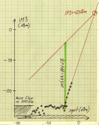
Fig. 1. Two-tone test with Perseus at 10.7 MHz. Preamp ON, Dither ON, Att 0dB. The measurements were made at a bandwidth of 15 Hz.
The Perseus. Hardware and software.The unit is designed by Microtelecom s.r.l. in Italy. The unit samples at 80 MHz and uses an FPGA to do digital downconversion , filtering and downsampling to an output suitable for transfer via USB 2 to a PC computer.Linrad-02-45 and later versions can use the Perseus hardware for input. Besides the software, perseus.exe that Microtelecom supplies with each unit and on their web site, Perseus can also be used with Winrad which can be downloaded from The WEAKSIGNALS pages of Alberto, I2PHD Linrad is more complicated than Perseus or Winrad and has a much steeper learning curve. On the other hand Linrad allows far more special settings that are optimized for various purposes. Waterfall sensitivity.The perseus allows an output sampling rate of 1 MHz with a full performance bandwidth of 800 kHz. This makes an excellent tool for searching for extremely weak signals on microwave bands where the total number of signals is low. This link Comparison between waterfall sensitivities explains why the Linrad waterfall is both much faster and much more sensitive than conventional waterfall graphs.Two-tone test for IM3.Analog receivers are usually well characterized by IP3, but A/D converters are not. The Perseus HF receiver has an intermodulation-free dynamic range of 104 dB in 500 Hz bandwidth with an IP3 of +27 dBm for signal levels above -20 dBm. At low signal levels, down to about -70 dBm, the signal at the IM3 frequency is at the same level as the internal noise floor in a bandwidth of 500 Hz, -125 dBm (NF=22 dB.) All these numbers are with dither, preamp and input filters enabled and with the attenuator set to 0 dB. See figure 1 for details. |
 Fig. 1. Two-tone test with Perseus at 10.7 MHz. Preamp ON, Dither ON, Att 0dB. The measurements were made at a bandwidth of 15 Hz. |
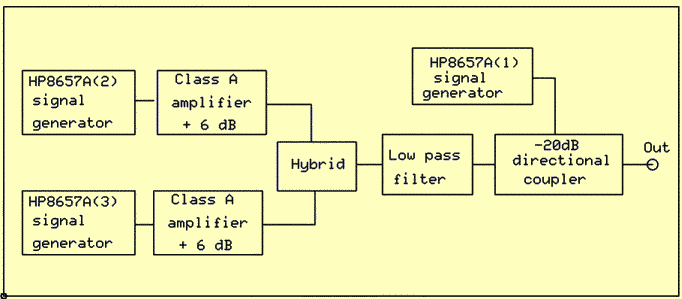
Two-tone test for IM2.Second order intermodulation can be a problem in Europe because of the strong broadcasting stations on the 41 m band.Figure 2 shows the test setup for IM2 measurements. For the test, generator 1 was set to 14.21 MHz while generators 2 and 3 were set at 7.1 and 7.12 MHz respectively. The output on 7MHz was +16 dBm for each tone and the "pilot tone" on 14.21 was set to -84dBm, 100 dB below the test tones. |
 Fig. 2. Setup for two-tone IM2 test. |
|
The low pass filter and the 20 dB coupler are designed with iron-free inductors so they should allow a very clean signal on 14 MHz, free from overtones and intermodulation generated in the class A amplifiers. The output is routed through a stepped attenuator into the test object. The "pilot tone" is used to calibrate the S-meter of the test object. (Linrad allows the S-meter to show dBm values.) Figure 3 shows the test result. |
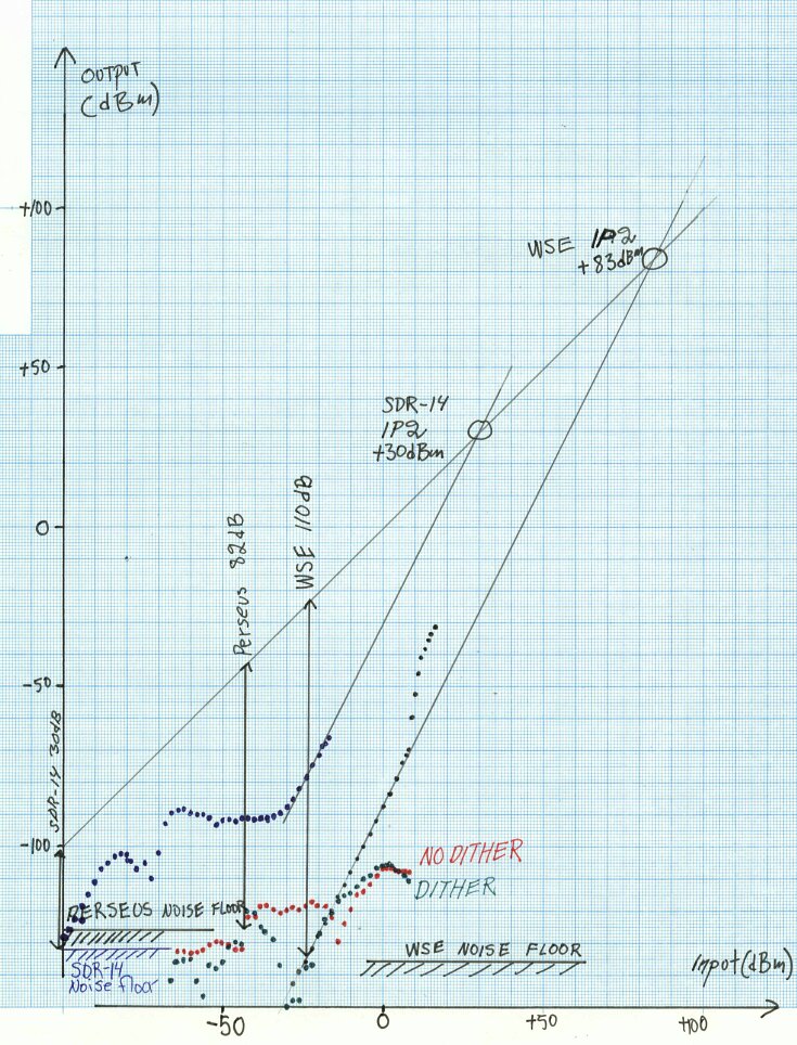
 Fig. 3. Two-tones on 7 MHz produce a sum frequency on 14 MHz. Perseus uses A/D converters while the WSE converters use analog technology. The measurements were made at a bandwidth of 15 Hz. Red and green points are Perseus with and without dither. Blue points are the SDR-14 and black points are the WSE converters. The noise floor levels in this image are for 500 Hz bandwidth. |
|
It is immediately clear from figure 3 that Perseus behaves quite differently from the WSE converter chain. The sum frequency on 14 MHz is well above the noise floor for 7 MHz signals down to -40 dBm. Inserting an attenuator is not a solution, the desired signal would drop, but the sum frequency would not. Adding a preamplifier would be a better idea as long as the level on 7 MHz would stay below 0 dBm. A simple tuned amplifier that has 10 to 20 dB gain on 14 MHz but that does not amplify on 7 MHz would bring the sum signal below the noise floor on 14 MHz. The IM2 tests on the Perseus were made with the preselector and preamplifier enabled. It is pretty obvious from figure 3 that the SDR-14 needs a preselector for usage on 14 MHz in Europe. The second order intermodulation-free dynamic range could be defined as the signal level where IM2 products are equal to the noise floor. With that definition, SDR-14 has IM2DR=30dB while the Perseus is at 82 dB and the WSE converters at 110 dB. With 40 dB of gain, the SDSR-14 would reach an IM2DR of about 60 dB but that would not be very useful since in-band signals would be likely to cause saturation. The SDR-14 needs an external preselector. To SM 5 BSZ Main Page |