Adaptive filter tuning for good pulse response
Crystal filters with good shape factors do not have very good phase response. The extreme IF filters using surplus crystals to get 20kHz bandwidth with an attenuation of 100dB 2kHz outside the 3dB points have very ugly pulse response with very long ringing after each pulse and makes this problem very clearly visible.The pulse response can be greatly improved by adding one more filter in the signal path. The optimum additional filter will correct nonlinearities in the phase response and modify the amplitude response for a good compromise between bandwidth and pulse shape.
The blanker init routine
To use this function the PC needs a pulse generator connected to both the receiver channels. The amplitude at the Soundblaster input has to be within 15dB from, but below saturation of the A/D converter.Fig 1 shows the normal receive mode spectrum when a pulse generator is connected to the receiver inputs replacing the antenna and preamplifiers.

Fig 1. Frequency response before initialisation as seen in normal
receive mode.
The peak at low frequencies is due to the IIR filter used in
the conversion from real data at 44kHz to complex data at 22kHz
sampling frequency.
The amplitude response of the crystal filter itself is reasonably flat
which is important for dynamic range performance but otherwise
insignificant - the blanker init procedure compensates.
By clicking at the box "Init" in the blanker window the operator can start the initialisation routine. The computer will collect a large number of pulses, calculate the fourier transform of each one of them. The transforms are expressed as an amplitude and as a phase slope function. These functions are independent of the phase and time of arrival of the pulse so they can be averaged over all the pulses.
The average amplitude and average phase slope is an accurate evaluation of the receiver filter response.
The actual pulse response of my system with extreme IF filters is shown in fig 2 which is one of the graphs in the noise blanker initialisation routine.
The average transform itself is shown in fig. 3 which is another output from the initialisation routine.

Fig. 2. Output from the blanker initialisation routine.
Each collected pulse is shown in this way.
The complex voltages of the two channels (the two upper traces)
differ slightly due to small differences in the hardware.
The bottom trace shows the total RMS voltage of this
particular pulse in yellow.
(Square root of sum of squares of all four traces above.)
The bottom trace also shows the average RMS voltage for all
pulses collected.
The average RMS pulse shape is used to decide if the pulse
is good enough to use in the average.
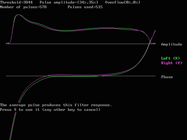
Fig. 3. The average fourier transform of the pulse response is an accurate evaluation of the amplitude and phase response of the receiver. This graph shows the amplitude in linear scale and contains the same information as fig. 1 but with far higher accuracy. This graph also includes more points outside the passband.
If the operator presses Y when fig 3 is shown, the initialisation routine calculates the filter required to make the total filter function equal to the desired filter function.
The desired filter function has the phase=0 for all frequencies and the amplitude=1 for all frequencies within the flat region with a parabolic fall off outside. The operator has to supply the end points of the flat region and the curvature (second derivative, which is a constant for a parabola) to use at each side. Fig 4 shows how the screen looks when suitable parameters are selected.
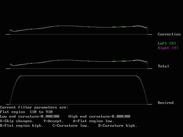
Fig. 4. By selecting reasonable parameters the desired
filter function can be made to fit the actual frequency
response reasonably well.
Once the operator pressed "Y" to the graph in fig. 4, the amplitude function "Total" will be used together with the inverse phase of fig. 3. to create a filter. ("Total" is equal to "Correction" because there is no old filter function during init)
The blanker "Init" function will not give a perfect correction filter, but it gives a good improvement. Still with the pulse generator connected to the antenna inputs the operator should click on the "Improve" box several times to refine the correction filter.
The improve routine is similar to the init routine, but is
includes the digital filter already established.
When running improve for the first time the output typically
looks like in fig 5,6,7 and 8.

Fig. 5. One of the collected pulses during first run
of blanker improve.
This figure corresponds to fig 2.
Note that the pulse shape is drastically improved in
the sense that the pulse is much shorter.
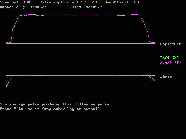
Fig. 6. The frequency response recorded during the first
run of blanker improve.
This figure corresponds to fig. 3.
The amplitude and phase functions shown here is the total
amplitude and phase response of the PC receiver when the
digital filter determined by the blanker init routine has
been inserted in the signal path.
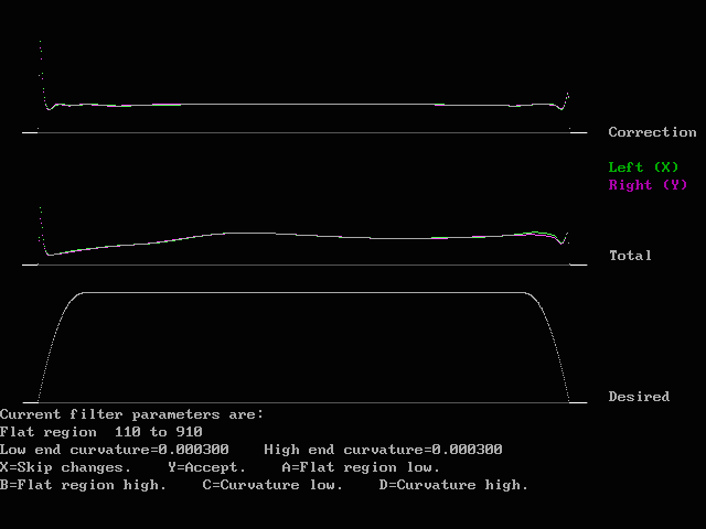
Fig. 7. This graph corresponds to fig. 4 and was produced during
the first run of the blanker improve function.
The correction filter that has to be added in order to make
the total frequency response equal to the desired
frequency response has somewhat large values towards the
passband edges.
The "Total" amplitude function is the product of the old
amplitude and the correction determined during this particular
run of the improve function.
The flat region of the desired filter has to be made slightly smaller
to avoid very large values at the ends of the "Total" curve during
the next run of the blanker improve function.
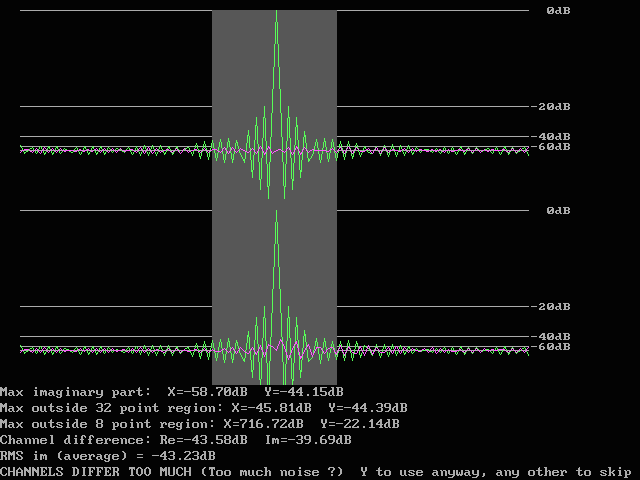
Fig. 8. The average pulse response in signed logarithmic scale.
Output from the first run of blanker improve.
The average pulse is here centered on a sampling point and the phase
is selected to be 0 degrees (real).
Note that most of the power is in a single point.
The surrounding points are 20 dB down so they contain 1% of the maximum
power each.
The grey region is the 32 point region which is the size of the
stored standard pulse.
After several runs of the blanker improve routine with appropriate changes of the flat region to avoid excessive values in the total amplitude for the digital filter the converged output from the blanker improve routine is typically as shown in figures 9 to 12.
The size of the flat region and the curvature of the parabolic fall off at the sides influence the pulse response. Since the noise blanker uses 32 points when subtracting very large noise pulses it is a good idea to select parameters that make most of the oscillations stay within +/- 15 points from the pulse maximum. Smaller pulses are subtracted by use of 8 points only to save time. Therefore it is a good idea to select parameters that give a modest amplitude outside +/- 3 points also to allow the faster pulse subtraction more often.
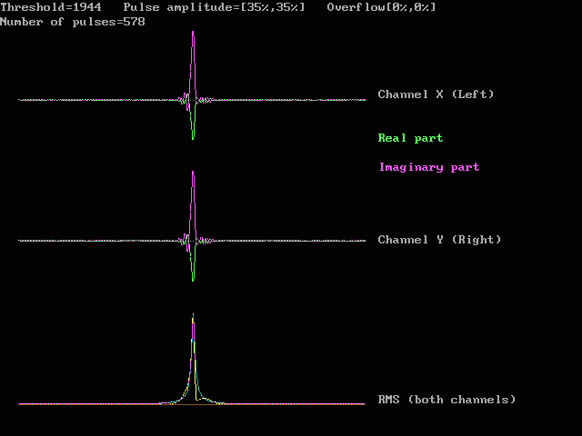
Fig. 9. Typical pulse shape of converged noise blanker improve.
The two channels are identical because both of them have a digital
filter in the signal path that makes the total filter response
identical to the desired filter response which of course is the same
for both channels.
This figure corresponds to fig.2 and fig.5.
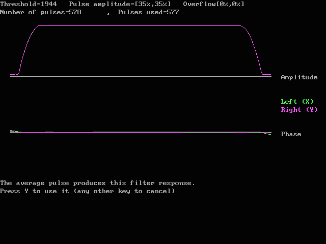
Fig. 10. The final frequency response for the PC radio with converged
noise blanker improve.
The amplitude and the phase are both accurately independent of
frequency within the passband.
(Outside the passband, where the amplitude is zero, the phase is more
or less undefined.)
This figure corresponds to fig 6 and fig 3.
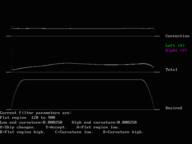
Fig. 11. When the correction curve is flat there is no reason to run
blanker improve more times since then no further changes will be made
to the digital filter.
This figure corresponds to fig 7 and fig 4.
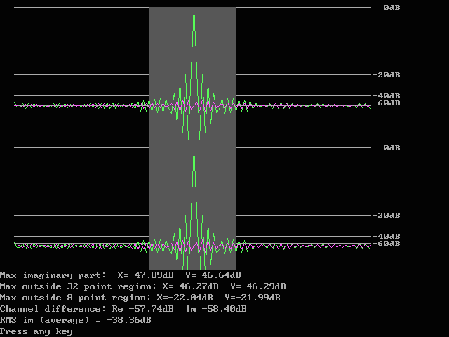
Fig. 12. The final pulse response with the parameters shown in fig 11.
The difference from the first iteration shown in fig. 8 is small.
The primary reason for running blanker improve several times is not to make
the noise blanker operation better.
It is to make the frequency response of the receiver accurately flat and
identical for both channels.
In this way the scale of the false colour graph can be made very steep
because the noise floor will have accurately the same level in the whole
20kHz frequency range.
With a very steep scale for the false colour graph signals producing
(S+N)/N of only a fraction of a dB become visible which means
that signals deep down in the noise can be seen.
Accurately identical responses in both channels means that the polarisation
calibration is accurately identical for all frequencies.