Vårgårda13 at 432.0 MHz

Fig 1. Vårgårda13 at 432.0 MHz.
The vertical scale is Voltage in arbitrary units. Horizontal is angle in degrees.
There is clearly a difference between the model and the measured data
for the forward ground reflection.
Otherwise the agreement is good.
Vårgårda13 at 436.0 MHz.
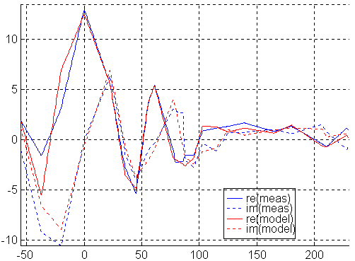
Fig 2. Vårgårda13 at 436.0 MHz.
The vertical scale is Voltage, same units as in fig 1. Horizontal is angle in degrees.
For this antenna 4MHz does not make much difference.
This figure is similar to fig. 1.
The back lobe of Vårgårda13.

Fig 3. The back lobe of Vårgårda13.
The vertical scale is Voltage, same units as in fig 1. Horizontal is angle in degrees.
In direction 180 degrees, the direct wave is nearly constant with real and imaginary components slightly above 1 unit. Together they form an amplitude about 18dB below the main lobe at all frequencies. The reflections from about 80 meters away have about the same amplitude, and they add to or subtract from the direct wave depending on the rapidly changing phase angle.
A single frequency measurement of F/B could produce
any value between -14dB (432.15MHz) and -23dB (at 433MHz)
and would not give any information about anttenna performance.
Vårgårda13 magnitude of error at all frequencies and directions
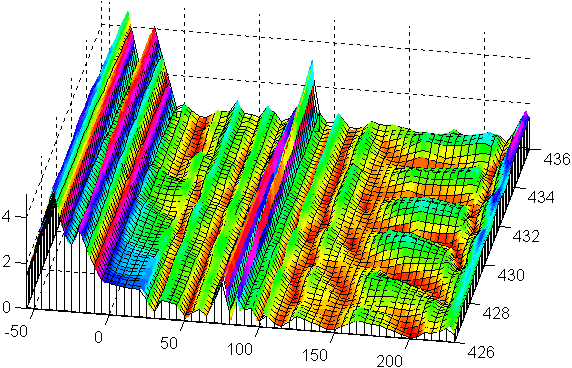

Fig 4. Vårgårda13 magnitude of error at all frequencies and directions.
The vertical scale is Voltage, same units as in fig 1. Horizontal are angle and frequency.
The magnitude of the direct wave is about 14 units. When the antenna points towards the ground between the towers the error is in the order of 5 units.
The pattern of vårgårda13 it is not particularly clean,
so the modest agreement between measurement and model is not unexpected.
There are several objects below the tower that may be seen by the
main lobe or the side lobes at negative elevations.
The method we use, rotating around a horizontal axis, is designed
for antennas with cleaner pattern.
Vårgårda13 real part of far field at all frequencies and directions.
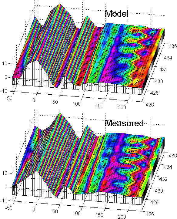

Fig 5. Vårgårda13 real part of far field at all frequencies and directions.
The vertical scale is Voltage, same units as in fig 1. Horizontal are angle and frequency.
The figure alternates between experiment and model.
Note that the reflection from behind can be seen as ondulations
at for example 0 and 140 degrees when the back lobe or the first side
lobe points at the reflections behind.
Since neither model nor measurement changes with frequency significantly
this image does not tell more than fig. 1 or fig. 2.
Vårgårda13 imaginary part of far field at all frequencies and directions.
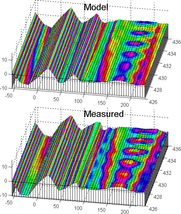

Fig 6. Vårgårda13 imaginary part of far field at all frequencies and directions.
The vertical scale is Voltage, same units as in fig 1. Horizontal are angle and frequency.
The figure alternates between experiment and model.
No particularly interesting difference can be seen between
model and measurement.
Cartesian plot of radiation pattern for vårgårda13.
img src="bilder/varg13/xyplot.gif" height="275" width="500" (image missing)Fig 7. Cartesian plot of radiation pattern for vårgårda13 at 432.0 MHz.
Despite the error at negative elevations, which may be due to some incorrect angle lable on the data files or due to inadequacies of the model in not taking objects close to the tower into account (or both) this radiation pattern and its associated gain figure are probably pretty accurate.
Polar plot of E-plane pattern for vårgårda13.

Fig 8. Polar plot of E-plane pattern for vårgårda13.
Same data as in fig. 7.
Polar plot of H-plane pattern for vårgårda13.
 Fig 9. Polar plot of H-plane pattern for vårgårda13.
Same data as in fig. 7.
Gain vs frequency for vårgårda13.
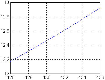
Fig 10. Gain vs frequency for vårgårda13.
This gain curve is calculated by integration of the corresponding radiation patterns. The gain values are with reference to the actual impedance of the antenna, not to 50 ohms.
The model fits very well to measured data for all frequencies except at negative elevations. Maximum gain is somewhere around 445MHz. The errors in the gain figures are probably small.