(Nov 19 2012)
NE334-S01.
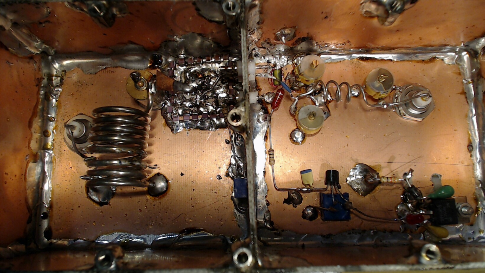
Directly from drain to the source ground plane is a RC link
10pF/100 ohms. The wire from the drain to the output side
is routed through a small ferrite tube that adds a resistive
loss of 3 ohms on 144 MHz and 11 ohms on 1296 MHz.
The drain goes to a phase inverter with 2x3 turns on a
BD 3.5/1.3/6-4S2 ferrite tube.
The midpoint is not grounded but connected to ground through
a 40 pF trimmer.
This trimmer is used to set the phase correctly to get a
deep minimum in the reverse signal.
DC is applied at the midpoint through an inductor.
The output is tuned with a PI-filter.
The drain voltage is set with a potentiometer followed by an
emitter follower to 1.29 V.
The source resistance is set to 49 ohms with another potentiometer
this gives a current of 9.8 mA through the transistor.
NE334-S01. Input impedance and forward gain.
NE334-S01. Output impedance and reverse isolation.