(Nov 20 2012)

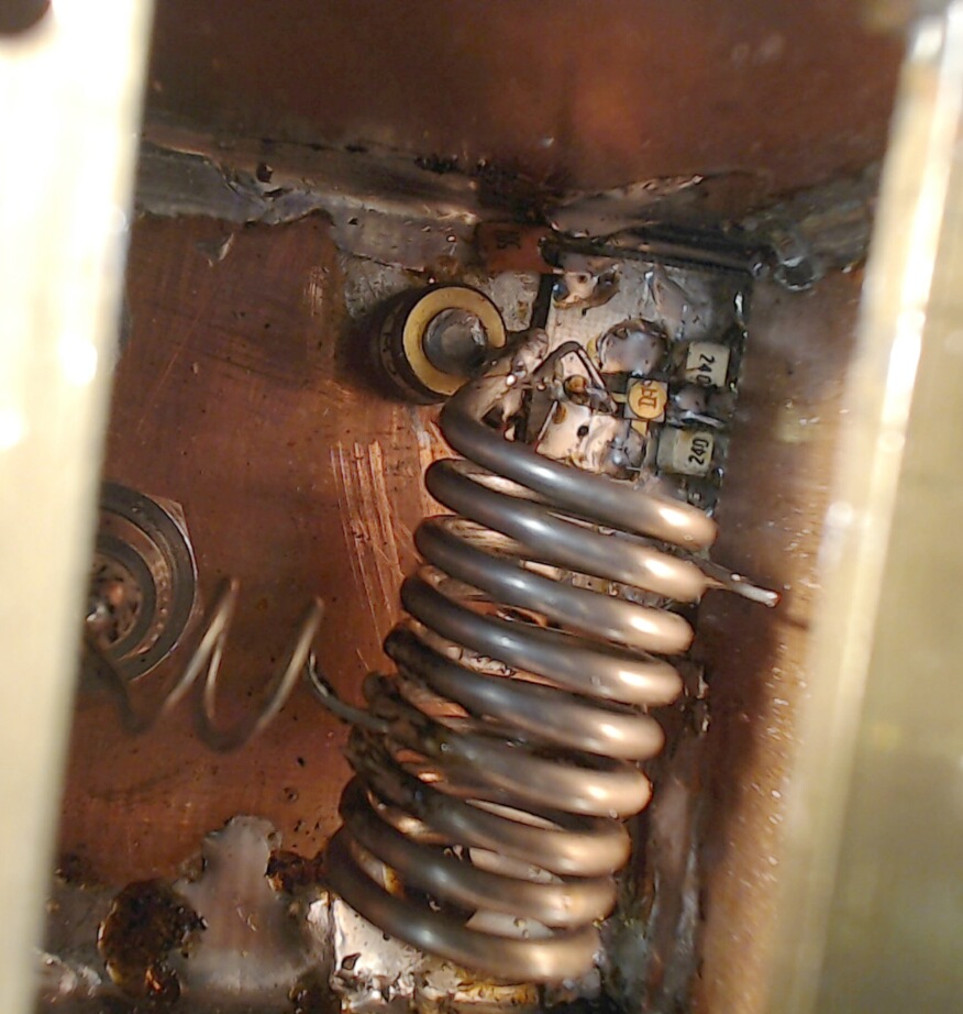
MGF1801. Input side.
Here one can see two low loss 24 pF capacitors from the drain to the
source ground plane.
The source ground plane is decoupled to ground with 8 capacitors
1 nF each evenly spaced around the ground plane and to the
screening wall between the input and output compartments.

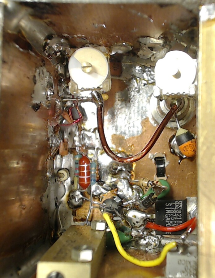
MGF1801. Output side. The output tuning is a PI filter.
The 48 pF fixed capacitance has a trimmer in parallel.
There is a DC blocking capacitor in between.
The inductance is a slightly bent 1.5 mm enameld wire and the output
capacitor is 33 pF with a trimmer in parallel.
The output could be re-tuned to 50 ohms, but since several
measurements have been made on this amplifier before I
decided to not change anything.
Neutralization is via a phase inverter made from a few turns
tvisted wire wound on a small ferrite tube.
The drain voltage is set with a potentiometer followed by an
emitter follower to 3.68 V.
The source resistance is set to 46 ohms with another potentiometer
which gives a current of 30 mA through the transistor.

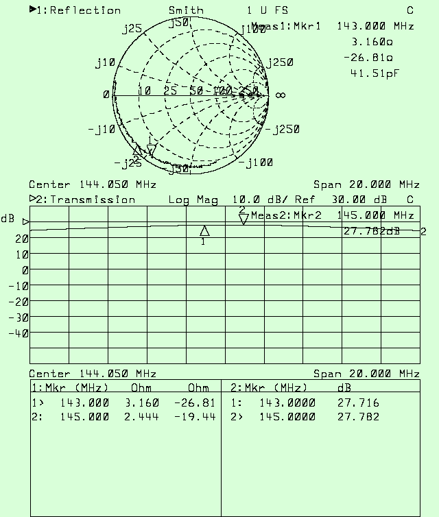
MGF1801. Input impedance and forward gain.

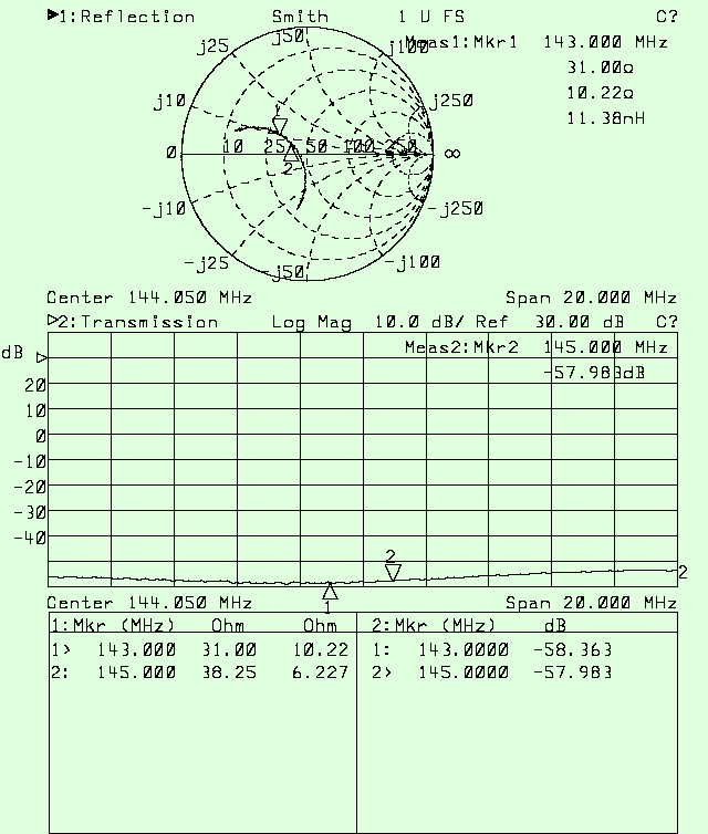
MGF1801. Output impedance and reverse isolation.


