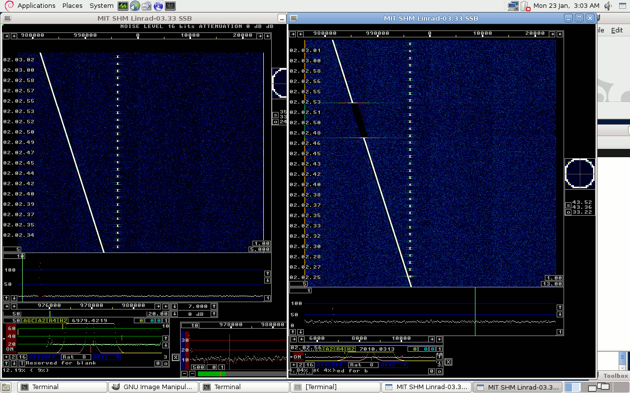
Basics.The computer has some kind of hardware that collects data into a buffer of some fixed size. When the buffer is full the input would start to fill the next buffer while the full one is sent away for processing.Errors of several kinds are possible: 1) Buffers are lost. 2) Incorrect buffers are sent away. 3) Buffers contain random data. Every processing stage through an SDR software makes the processing in buffers, and software errors can in principle cause any of the three error types. Digital decoders like MAP65 are based on precise timing. The software assumes that data is collected continuously at a speed close to the nominal sampling rate. Errors of type 1 above are likely to cause loss of detection regardless of the S/N because symbols would arrive at incorrect times. Errors of the second and third type would cause interference pulses but they would not be very harmful if they occur infrequently. Testing the Linrad software for errors.Linrad is now a multi-threaded software but it was originally developed as a single threaded program. Along the road there have been errors when some part was lifted out from the main program into its own thread. One example is versions 03-28 to 03-32 which had errors of type 1 above and therefore did not work with MAP65.Linrad-03.33 can be set to simulate a very strong signal plus a weak one on a random noise floor. By setting Linrad to transmit the simulated signal in the TIMF2 format and by running a second instance to receive the signal one can verify that Linrad does not introduce any glitches anywhere from the input buffer of Linrad to the network output. Such a test is demonstrated in figure 1. |
 |
|
Fig 1.The internal generator of Linrad displays a
glitch-free waterfall on the Linrad slave, right hand side.
That implies that the phase or amplitude of the strong signal
does not make any jump since errors would be likely to have an
amplitude that would be similar to the amplitude of the strong signal.
In the time interval 02.02.47 to 02.02.53 the strong signal components
of the TIMF2 data were blocked by clicking the box with "1" in
the high resolution graph.
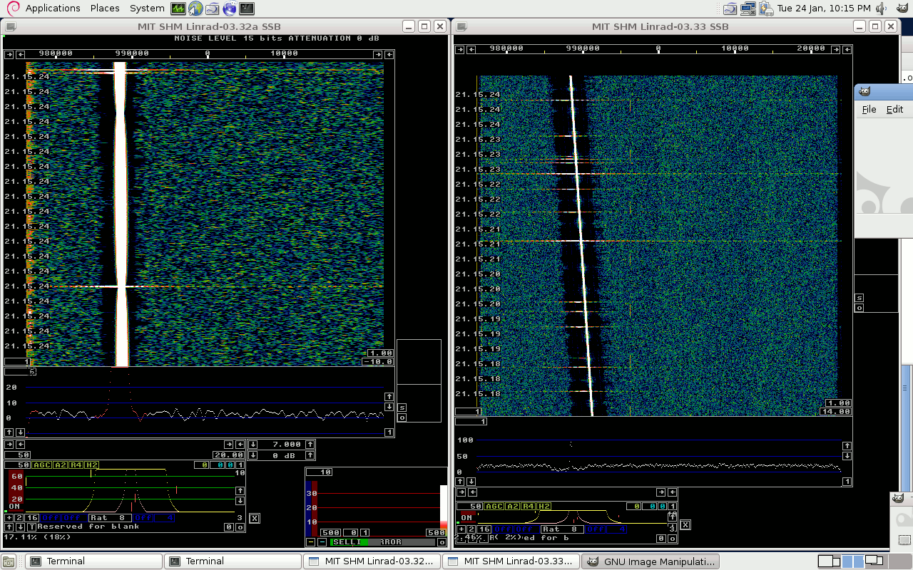
In case glitches occur, the screen could look like figure 2. Here Linrad-03.32a is used as the master to transmit TIMF2 data to Linrad-03.33. By selecting particular parameters a bug in 03.32a becomes visible on the dual core laptop on which which the test was done. Normal parameter settings make this bug invisible, it is caused by one thread using a scratch area belonging to another thread. The probability for this error is different on different platforms. In case you observe glitches, something is wrong. Then, please save all parameters and report the error. |
 |
Fig 2. An error in linrad-03.32a is visible both
in the master and the slave waterfall.
Errors in the network would only be visible in the slave waterfall.
Errors in the input device driver.Errors occur in the input device drivers due to various bugs in the driver or errors in unrelated drivers that cause excessive DPC latencies.Such errors can not be detected with the internal generator of Linrad but since they are not uncommon it is wise to look for them. Just send a strong signal into your receiver, run the waterfall without averaging at a couple of different FFT bandwidths and make sure there are no horizontal lines in the waterfall. It may be wise to force DMA rates well above and well below the ones actually used normally by use of max and min DMA rate in the menu U = A/D and D/A set up for rx. That would change buffer sizes and such a test would show if the buffer size is critical. (On a computer with DPC latency problems one would probably need fairly big buffers.) To SM 5 BSZ Main Page |