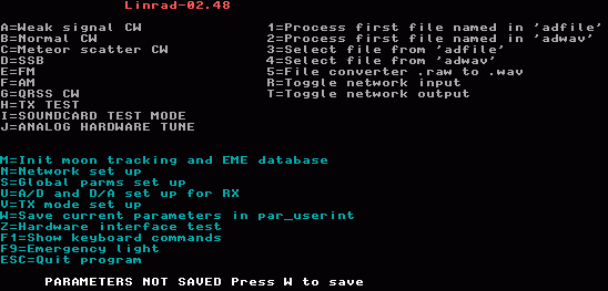
This page is intended to guide newcomers to a simple single channel receiver with good general performance without going into detail about the special features built into Linrad that sometimes allow an enhanced sensitivity.
What is LinradLinrad is a computer program for PC computers. When some kind of hardware capable of transfering a radio signal into the digital domain is connected to a computer on which Linrad is running, the entire system is an SDR. A Software Defined Radio.This page only describes limited aspects of the receive side, but with suitable hardware Linrad can also be used as an SDR transmitter, transceiver, radar, test system and many other things. There is a long history behind Linrad. The first systems were completely analog with filter banks rather than FFT computations. The first digital system, built in 1995, was implemented on a TMS320C25 and could find and filter out extremely weak signals from a bandwidth of 3 kHz and was extremely helpful in EME contesting because it allowed efficient use of both signals from a cross yagi array. The next generation, 1998, used a Pentium MMX and allowed 20 kHz bandwidth under MSDOS. On this system both the good old wideband noise blanker and a new digital noise blanker helped to keep the noise floor low. In year 2000 when I decided to rewrite the MSDOS program completely, the limitations due to high cost for compilers and memory management programs led me to change operating system to Linux. I really wanted to share the program code with everyone who might be interested in order to get ideas in return as feedback. I could not expect amateurs to pay USD 500 just for a compiler plus a substantial amount of money to be able to use more than 32 megabytes of memory with DOS4GW. In Linux everything was free!! The DSP program was named Linrad but in recent years this name is a bit misleading. Since 2005 Linrad can be used under Microsoft Windows also. The Linrad executable compiles under Linux as well as under Microsoft Windows (98, ME, 2000 and XP) from the same set of files using the free compilers mingw32 and nasm. Open source programs usually have a license. Linrad does not. It is free, without copyright and it can be used by anyone for any purpose. Hardware needed between the antenna and the computer.Linrad itself is just a computer program. To get an SDR one needs something that selects a part of the RF spectrum from the antenna and converts it into digital form. For convenience everything up to the point where the data first is represented in digital form inside the PC computer will be named radio hardware on this page. This means that a soundcard that is placed inside the computer and that is used to digitize an audio signal is part of the radio hardware in the meaning of the word on this page.Linrad is quite general and can be used with a wide range of hardware. When I started rewriting the MSDOS package back in 2000 I decided to write for the VHF-sampling receivers that one could forsee would become the standard architecture in the future. At the same time I wanted Linrad to be a full-valued replacement for the old TMS320-C25 system because it would run on computers that were obsolete already in year 2000 and therefore easily available to young experimenting amateurs. Types of radio hardware
What kind of radio hardware to select for Linrad depends on what you want to achieve. The most important factors are bandwidth and dynamic range. It is a complex issue but it is often not critical at all and for the purpose of this page the choice of radio hardware does not matter much. Should you find that you need better radio hardware you can always upgrade. Linrad will behave the same except that the noise blanker will function much better with large bandwidths. Computers for use with Linrad.The computer needed to run Linrad has to use the x86 architecture and to be compatible to a 486 processor. The processor speed (model and generation) needed depends mainly on the desired bandwidth, but the computer must of course be modern enough to allow the desired operating system.Today the CPU speed is not often the limiting factor any more. This list gives an idea about what computers would be suitable for a newcomer at different bandwidths: Bandwidth Computer Radio hardware 5 kHz Pentium 100 MHz Type 2 96 kHz Pentium II 350 MHz Type 3 180 kHz Pentium III 650 MHz Type 4 250 kHz Athlon 850 MHz Type 4 500 kHz Pentium IV 2.7 GHz Type 4 1 MHz Centrino Duo 2 GHz Type 4An experienced Linrad user can run much more bandwidth on slower computers, but with the excess capacity that computers selected according to the list will have, newcomers can set parameters that are far from optimum without any loss of system performance. Operating systems.The different operating systems that can be used for Linrad are:
If you find computers and various cards for Ethernet, USB, sound and video at flea-markets or at the local waste collection point, it will be a good idea to select Linux as the operating system because it may be hard to find drive routines for Windows to unknown hardware. If you have a working computer and only have experiences with Microsoft Windows, it will be a good idea to use the computer as it is. As a newcomer to Linrad your choice of operating system is not important. Linrad always behaves the same with computers having sufficient CPU power to make the modest differences in timing between operating systems insignificant. Installing Linrad.The Linrad program is a single executable file plus two plain text files that contain help texts and error messages respectively. The installation of Linrad is simply to place the executable and the two help files in a separate directory.During setup and calibration Linrad generates files in the currently logged directory and it is a good idea to start Linrad from there. It is a good idea to keep separate Linrad directories that contain a complete backup of everything whenever a new version is installed or when you make changes to the hardware or to the parameters. It is possible to set parameters that make it impossible to start Linrad and it is then practical to have the possibillity to restore everything with a command to copy the backup directory on top of the one that does not work. The parameters are plain text files and they can be modified with a text editor which may be much faster than going through the setup procedures. The executable file is: linrad (for Linux in console mode) xlinrad (for Linux under X11) linrad.exe (for Microsoft Windows) The executable can be produced from source code with two commands configure and make in case the source code package is present in the Linrad directory. Under Windows you can also download the .exe file and the message files as a .zip file. More information about installing Linrad can be found here: Linrad Home Page Installing everything else.The Linrad executable is self-contained and it does not require external libraries for mathematical functions etc. It does however require that drive routines are installed in the operating system to give Linrad access to the hardware that the operator wants to use. It could be any or all of these:
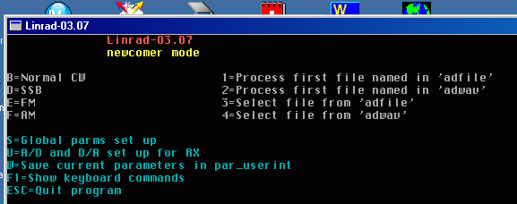
There are advantages with running Linrad under Linux. If you have no expereince at all with Linux, follow the detailed instructions for some of the popular Linux distributions. These instructions on how to install Linux and Linrad on a computer do not require any previous knowledge of Linux or Unix. Actually not much previous knowledge at all. Global parameters setup.Once Linrad is installed - and regardless of whether most of the drive routines for the hardware is correctly installed or not you can start Linrad and if it is the first time you will be prompted for S to enter the system setup menu. or N for newcomer mode In newcomer mode Linrad is much easier to understand. Many options are disabled and it will be a good idea to use Linrad in newcomer mode while you first get acquainted with it. (S on the main menu will give the system setup and a chance to exit from newcomer mode.)Under Microsoft Windows or Linux X11 the only global parameters you can set in newcomer mode is the screen size (as a percentage of your screen.) Make sure the screen is at least 800x600 pixels. In normal mode the first choice is what font size to use. Linrad has its own fonts, the smallest is 8x8 pixels and the largest is 16x24 pixels. Equal for all operating systems. What comes next is a little different on different systems but what to choose should be pretty obvious. Once the Global parameters for keyboard, screen and mouse are set (mostly to defaults in newcomer mode) you should arrive at the main menu. As you can see, the menu in newcomer mode is shorter. |

|
|
|
|
|
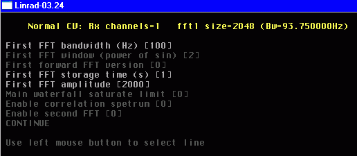
There are more global parameters to set, those for your radio hardware, but if the screen looks good, save your choices by pressing W so you will not have to repeat this step if something goes wrong. The next step is to select the interface to the radio hardware and the soundcard for the loudspeaker/head-phones. Press U to enter the A/D and D/A setup for the receiver. What will happen depends on your hardware and its associated drive routines and whether or not you are in newcomer mode. Make the selections you think will be appropriate for your hardware. It may be a good idea to not select the highest possible sampling speed if it is the very first time on a new hardware. One selection in the A/D and D/A setup menu is a limit for the highest and lowest DMA rate you are willing to allow for the soundcards and other devices. These parameters have default values in newcomer mode. In case min is set low and max is set high Linrad would make a guess based on other parameters selected for each processing mode. By setting both min and max to the same value (high or low) Linrad would be forced to set a buffer size that would give the specified DMA rate. In case that would not be acceptable to the hardware Linrad would set the nearest possible buffer size to get as close as possible to the desired DMA rate. A high DMA rate will cause more overhead and could (in principle) cause problems. A very low DMA rate will make it more difficult to synchronize the output to the input. These parameters are primarily motivated by timing issues when Linrad is used as a transceiver in radar mode. I do not know whether very large or very small values on these parameters will have bad effects on a receive only system. After exiting from the A/D and D/A setup menu. Press W to save the new parameters if it is the first time. In case you change something without pressing W you may check what the effects are and then restart Linrad to get the original parameters back. The global parameters depend on your computer hardware and on the digital interface to your radio hardware. The idea is that these parameters should never be changed once the optimum parameters have been determined. There are four kinds of global parameters. Those related to the computer, those for the receive input/output and those for the transmit input/output and the network enable/disable controls. Whenever any parameter within these categories has been changed, it is necessary to press W to overwrite the previous settings. Mode parameters. First time.Linrad can be configured in many different ways but the system performance of the SDR that Linrad and its associated hardware can deliver depends on signal levels and noise levels of the radio hardware. The very first step in the Linrad setup procedure is therefore to set the signal levels of the radio hardware correctly. Linrad is an excellent level meter and the first time setup of a receive mode is designed to make it very easy to adjust the hardware properly.Press B on the main menu to enter the normal CW receive mode. The very first time you will be prompted to the mode parameter selection routine automatically. Later you have to press X, then P to enter the mode parameter select menu from the processing screen. The mode parameter select routine has several sub-menus. The first screen looks like this in normal mode: |
|
|
Set your parameters as shown here.
In newcomer mode you can only change three of the parameters.
The screen dump shows the default parameters.
If you are not in newcomer mode you can enable the second FFT and get a parameter screen for that. The next screen is not available for newcomers, it is shown here to give an idea about things it will be a good idea to wait with until you are familiar with the basic operation of Linrad. |

|
|
If AFC/SPUR/DECODE were enabled there would be one more screen of things
a newcomer should wait with.
The last mode parameter screen may be different on different systems. It could look like this in newcomer mode: |

|
|
In newcomer mode you can only change three of these parameters.
The input bandwidth to Linrad is determined by the radio hardware
while the final filtering is done at a lower sampling rate.
The first parameter determines by how much the sampling rate
should be reduced.
A small value here will send a large bandwidth to subsequent
processing stages and that is normally not what one would
want in a CW mode,
but during the first stage setup it is a good idea to use
a large bandwidth because then the S-meter gives stable
average values on the noise floor in a short time.
The selected value 2 means that the bandwidth is reduced by a
factor 22 = 4.
This is suitable at an input bandwidth of 96 kHz (direct conversion
with two audio channels I and Q at a sampling speed of 96 kHz.)
The sampling speed that reaches the baseband filter in Linrad
will then be 96/4 = 24 kHz.
The actual bandwidth is a bit lower,
there are anti alias filters inside Linrad that attenuate signals
outside the desired 24 kHz range and they also attenuate signals
near the passband edges.
Set the output sampling rate high, 48 kHz is a good choice.
Linrad will not allow a bandwidth that is greater than
the bandwidth your output soundcard can handle so a low
sampling rate on the output would make the bandwidth smaller.
With 48 kHz sampling rate for the loudspeakers,
the Nyquist frequency is 24 kHz and that matches the maximum
bandwidth of the baseband processing when the first mixer
bandwidth reduction is set to 22.
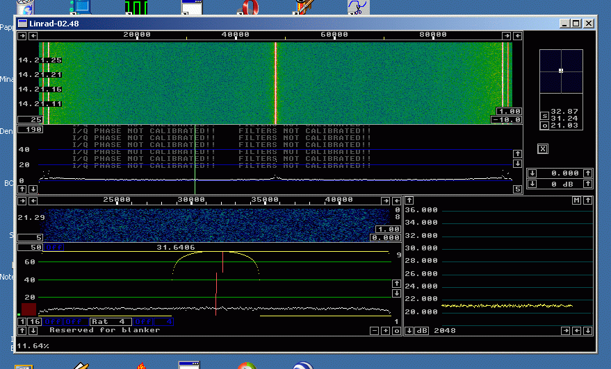
With a large bandwidth it is important to set a small value for the baseband storage time. Set 5 s, the minimum value. Increase later in case you want longer times for averaging. Very long times are intended for advanced Morse decoding with correlation of waveforms over several minutes. The bandwidth is then very narrow and not much memory would be used. If too much baseband data is stored, your computer will use the hard disk rather than RAM and that could cause various timing problems. The other parameters are not important at this stage. In case you want to know more about the parameters, place the mouse cursor on one line and press F1 to get the corresponding help text from help.lir. The mode parameters are saved in par_wcw for weak signal CW, par_cw for normal cw and in par_ssb for SSB etc. There are files like par_cw_wg for the run-time parameters of the main spectrum and waterfall in normal CW mode, par_cw_hg for the high resolution graph, par_cw_bg for the baseband graph etc. In total a large number of plain text files. When leaving the last mode parameter screen you will reach to the processing screen with the parameters that you just selected. It will not look exactly like this image: |
|
|
but you should be able to get something similar by use of the
mouse and keyboard.
You may move the windows around to make the screen suit your taste.
It has to be done by moving border lines and sometimes one has to
move the other side first because the window size might be restricted.
It may also be necessary to move another window first because windows
avoid each other.
The entire process of moving windows is not particularly user-friendly,
but the idea is that you should not move them at all once you have decided
what you want for a particular mode.
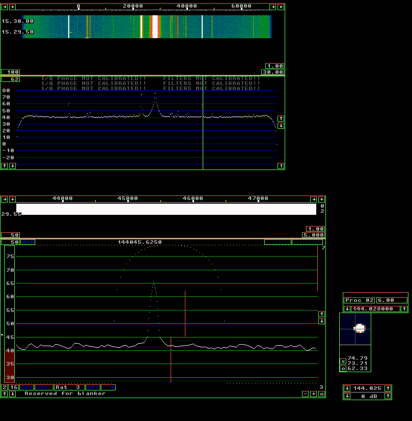
You may arrange your screen for a nice looking like the one shown here, but the only important thing during the first set-up is the S-meter. Note that the graph is flat despite the rather high speed. The S-meter draws new pixels at a rate of about 10 pixels per minute and yet the values are all within 0.25 dB from the true average. The reason is of course the large bandwidth, about 23 kHz. The mode parameters for the first step of the Linrad setup procedure are suitable for noise figure measurements, tests of sun noise and galactic noise in EME systems and Y-factor measurements in general. Place the mouse on an empty space outside the windows and press F1. This will show where all mouse controls are like this: |
|
|
All control areas are rectangular.
Three sides become green and the fourth side red when F1 is pressed
with the mouse placed where no mouse function is defined.
The red side moves slowly counter-clockwise around each control area.
Control areas are generally within a window, but an entire
window or parts thereof may also be a mouse control.
The border lines are also mouse controls.
Press any key to return to the normal processing screen. Then place the mouse inside one of the control areas (or a border line) and press F1 again. In case the area in the baseband graph with the numbering 30, 35, 40,....,75 was selected when F1 was pressed, the corresponding message from help.lir would be displayed like this: |

|
Take some time and investigate the Linrad screen with the F1 help.
In case something is unclear, post a question to the Linrad
mailing list
https://groups.google.com/g/linrad
There is room for much more information in help.lir....
Setup procedures for the radio hardware.All building blocks in a signal processing chain have an internal noise floor as well as an upper limit that no signal must go above. An SDR like Linrad may have a very large number of sequentially connected processing blocks. There is no fundamental difference between analog blocks, digital blocks or blocks that do conversion from analog to digital or vice versa.Ideally all the processing blocks should have a noise floor that is low enough for the antenna noise to dominate completely. This is easy on HF bands, but impossible on microwaves when the antenna looks into the cold sky like a modest size EME antenna. One can always improve by adding (yet another) low noise amplifier near the antenna, but in case the radio hardware uses several amplifiers, the dynamic range may suffer badly. The improvement may become vanishingly small in case the noise figure of the added amplifier is not much better than the system noise figure of the entire receiver chain that it is put in front of. The purpose of the first step of the Linrad setup is to make sure that the noise floors of the different analog processing blocks as well as the final analog to digital conversion step are placed properly. Actually this setup procedure is not specific for Linrad nor for SDRs generally. The same procedure should always be used in every receive system where optimum performance is desired. Analog as well as digital, regardless of frequency band. It is a quite simple test. Disconnect the DC supply to the first amplifier and make sure the noise floor falls by at least 15 dB. There is also a second, less simple test. Once the DC voltage is removed from the preamplifier, the noise floor should not change much when any other processing block preceeding the bandwidth limiting filter is disconnected. In analog receivers we hope that someone else already did the job for us, but in an SDR system like Linrad this is something that the user himself has to be responsible for. (Actually many EME-ers would find they have problems if they would do this test on their completely analog receive systems.) As a first example, consider an EME system for 144 MHz (my personal favourite.) We split the system into three separate building blocks:
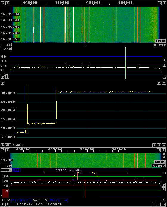
The digitizer is whatever unit that provides the digital output and from which we can not easily split off any processing block. The converter is everything in between. It could be a simple 144 to 28 MHz converter in which case the digitizer could be an SDR-14, a Perseus or some other VHF sampling receiver. The converter could also be any direct conversion radio used to convert from 144 MHz to audio followed by any stereo soundcard for the digitization. This figure shows the test with the chain of WSE converters RX144, RX70, RX10700 and RX2500 converting from 144 MHz to audio and with a Delta 44 (modified) as the digitization unit. |
|
|
Note that the bandwidth is reduced to about 12 kHz to avoid
some of the stronger spurs.
It is perfectly OK to reduce the bandwidth to any arbitrarily low
value but the time it takes to get a reading from the S-meter
within 0.5 dB would increase in proportion.
The S-meter shows three noise levels:
The number of dB that your noise floor rises when the DC voltage to your preamplifier is switched on gives directly the factor by which the noise floor power increases. Power is additive. It must be because it is energy per time unit and energy is conserved. One of the most fundamental laws of physics. Knowing by what factor the noise power increases we can compute what fraction of the total power that does not originate in the preamplifier or antenna. This fraction causes a loss of S/N and this table gives some numerical examples: ON/OFF-factor | Power split | S/N loss (dB) (PWR ratio) | Bad Good | (PWR ratio) (dB) 1 1.26 | 1 + 0.26 | 4.85 6.86 3 2.00 | 1 + 1 | 2.0 3.01 10 10.0 | 1 + 9.0 | 1.11 0.45 15 31.6 | 1 + 30.6 | 1.03 0.128 16 39.9 | 1 + 38.9 | 1.026 0.111 17 50.1 | 1 + 49.1 | 1.020 0.086 18 63.1 | 1 + 62.1 | 1.016 0.069 19 79.4 | 1 + 78.4 | 1.0128 0.054 20 100 | 1 + 99 | 1.0101 0.043 21 126 | 1 + 125 | 1.0080 0.035 22 159 | 1 + 158 | 1.0063 0.027 23 200 | 1 + 199 | 1.0050 0.022Judge from the table whether the noise floor shift that you observe when switching your preamplifier off/on is sufficient for your needs. In case the change is too large, you can improve the dynamic range of your system by inserting attenuators or otherwise reduce the gain. Note that there can be a pit-fall in the A/D converter. In case the internal noise floor of your A/D converter is very low you might observe a noise floor that does not represent the true value because the digital value seen by the computer is the same most of the time. A noise floor that stays between two of the discrete levels of an A/D converter will seem to be zero since the A/D output word is always the same. The phenomenon can be observed in good 24 bit soundcards in case they are used for 16 bit input and even more clearly in SDR-14 and SDR-IQ when the AD6620 chip inside the unit is not set up properly. To verify that the noise floor reading you observe without anything connected to the digitizer is correct, connect a sine wave signal source to the input and verify that the noise floor does not rise when the signal level is set high enough to sweep several A/D steps. In case you want to split your signal to feed several different receivers you should perform the tests for all receivers while keeping the hardware configuration unchanged. It may turn out to be a good idea to split the power unevenly and/or to use an uneven distribution of amplifiers and attenuators to allow all receivers to see the noise floor for which they are designed. There is a lot written on the Internet and elsewhere about how to set the gain distribution through a receive system for optimum noise figure and dynamic range. The purpose of this section is just to stress the importance of actually doing it for your SDR system. Linrad makes it very easy since it has a built-in dB meter. The digitizer might have several input connectors as well as builtin attenuators and amplifiers. They have all to be optimised for the hardware you connected to the soundcard. There is some information here: Analog signal levels. Note that the observed noise floor from your antenna may vary from time to time. Make sure that you have a small S/N loss at times when your local noise floor is at minimum. In case you need a better dynamic range occasionally, insert a switchable attenuator at a suitable place. Also note that the best noise floor that you observe in the first setup might not be the true noise floor. You may find that the noise floor decreases when you enable the Linrad noise blanker. The noise from your digitizer will be unaffected and as a consequence you may find it necessary to increase the preamplifier gain or do something else with a similar effect. Special considerations for SDR-14 and SDR-IQ.When you set up these units for the first time, select 0 for the RCF output shift parameter. The AD6620 chip inside the SDR-14 or SDR-IQ produces 24 bits of data but the USB link can only transfer 16 of them to the PC. By setting the RCF output shift to zero you will use the lowest bits and this way you assure that the internal noise floor of the unit is truly represented on the digital side.Then adjust the gain through your signal path from the antenna all the way to the A/D converter. The attenuator and/or amplifier inside the SDR-XX should be a part of this procedure. Once you have found the radio hardware that suits your needs, stay with these gain/attenuator settings and change the RCF output shift to place your noise floor at a level suitable for Linrad. This can not be done without a compromise because 16 bits does not quite match the dynamic range of the chips inside the SDR-XX. If the bandwidth is set to 148 kHz, the ideal value for the RCF output shift would be 4. This would use all 16 bits and cause an overflow on the USB line at the same input level where the red light on the unit indicates that the A/D converter saturates for a single sinewave that falls within the frequency ragion that is sent to the PC. This table shows the noise floor at different settings for the RCF output shift. RCF No signal -75 dBm shift (S-meter dB) (S-meter dB) 0 35.7 37.3 1 29.9 31.4 2 24.0 25.6 3 18.6 20.2 4 8.6 15.8 5 -25 13.5 6 undef 10.0 7 undef 5.1The sinewave at -75 dBm must be within the visible passband to create the effects of this table. For a signal outside the visible window the choice of which bits to transfer over the USB link does not matter because the signal is not inside the frequency range of the USB channel. Another interesting effect can be observed though: Level S-meter (dBm) (dB) -75 37.3 -80 37.0 -85 37.3 -90 36.7 -95 36.0 -100 35.7 -105 35.7This table shows the noise floor level for different levels of a signal outside the visible window. Whether this effect is due to the A/D converter or due to rounding errors in the AD6620 is unknown to me. If there are strong signals outside the visible passband one can safely set the RCF shift to 2 because then one can expect the summed amplitude of all signal that reach the A/D converter to be at least 12 dB above the summed amplitude of all signals within the passband. Should however the close spaced signals dominate it is necessary to set a shift of 4 in case the total amplitude is near A/D saturation. Direct sampling receivers like SDR-14 and Perseus should always be operated at the highest convenient signal level. Tha A/D chip produces digital data that couples back to the wideband input and causes false signals. By operating with an elevated noise floor one can hide the false signals in the noise. For this reason the general rule that says it is good to have a small increase of the noise floor when connecting the converter to an SDR-14 is not fully true. It indeed gives the best dynamic range, but not spurious-free in all situations. Mode parameters. Step 1.At this point the digital data stream that enters into Linrad should be optimized. It is now time to decide how to make the first processing step and to set the signal level properly on the digital side.Press X on the processing screen and go to the parameter setting function and try the different FFT implementations by changing "First forward FFT version". Look at the CPU load in the lower left corner of the receive screen and do not click on any signal to make the computations of the first fft dominate the processor load. The load may vary with the fft implementation or it may not. It depends on the processor architecture, cache memory, what FFT size you have requested etc. If one of the immplementations is significantly faster, select it! During normal on air operation the noise floor should be somewhere around 20 dB on the blue dB scale in the main window because the arbitrary dB scale has its zero point near the internal noise level of todays soundcards and the procedure outlined above will typically place the antenna/preamp noise 20 dB above the internal noise of the A/D converter. Should your noise floor deviate significantly from 20 dB, use the parameter "First FFT amplitude" to shift the spectrum up or down as required. The parameter is in linear amplitude so going from 1000 to 2000 will shift the spectrum 6 dB upwards. The mode parameters affect memory allocation. The first FFT storage time is 4 seconds by default. The very first time you should set this time to zero to minimize memory usage. Finally, on the first screen of the mode parameters, set "Enable second FFT" to 1. On the second mode parameter screen, make sure you set "Second FFT storage time" to zero. It will not allow averaging spectra over long times, but it will make sure your computer does not run out of memory. Leave the other parameters at their default values for now. Do not enable the AFC/SPUR/DECODE at this time. The very first time it is better to run Linrad like a conventional receiver. Go back and change parameters to allow more advanced functions when you are familiar with the simple functions. On the last screen you should set the "First mixer bandwidth reduction" to a large value. There is no reason to process excess bandwidth. The following values can serve as guidelines: Rate Hardware Mix1 bw parameter (kHz) Type CW SSB AM 5 1,2 1 - - 11 1,2 2 1 - 24 1,2 3 2 1 48 3,4 4 3 1 96 3,4 5 4 2 192 3,4 6 5 3 500 4 7 6 4 1000 4 8 7 5 2000 4 9 8 6What sampling speed to select for the output may depend on your hardware as well as on your operating system. For CW there is no need to select more than 5 kHz while SSB would require 8 or 11.025 kHz. For broadcast AM 24 kHz might be desireable. In case your soundcard actually only can do 48 kHz and relies on the drive routine or the operating system to do the rate conversion it could be better to allow Linrad to send data at 48 kHz, but it could also be better to send a lower rate. It is VERY important to set the "Baseband storage time" to its minimum when large filter bandwidth are used. The minimum may be different in different modes and may change in different Linrad versions. It is always safe to type in zero to get the minimum value. Linrad allocates a large number of buffers for baseband information. They all have a sampling rate that is about four times the selected filter bandwidth and too large data areas will surely cause problems because the operating system will silently use "virtual memory" i.e. your hard disk and that would cause timing problems. After having set parameters as described above, the Linrad screen should look something like this: |

|

|
|
Linrad locates peaks in fft1, the main spectrum. Peaks above a certain level are classified as "strong" and the associated point in the main spectrum is coloured red. The signal is then back-transformed to the time domain in timf2, but red and white frequency bins are kept separate which means that the back transformed white points do not contain any strong signals. They are notched out. The blanker operates on the the signal formed from the white points only. Once the blanker has finished its job the strong signals are added and the sum is transformed to the frequency domain again by the second FFT. The second FFT power spectra are displayed in the main waterfall and if the user has clicked on a signal the spectrum surrounding that signal will be displayed with one pixel per FFT bin as the high resolution spectrum, the window with a red dB scale. In situations when the interference level due to impulse noise is very high, the noise floor in the high resolution spectrum can be much lower than the noise floor in the main spectrum. Narrowband signals may then have a much better visibility and therefore Linrad also looks for narrowband signals in the high resolution spectrum and uses that information also for the notch filter function. At the left side of the high resolution window there are two vertical bars. The blue controls the level above which peaks in the main spectrum have to reach in order to be classified as strong while the red bar controls which peaks in the high resolution spectrum to classify as strong signals. Since the second FFT is produced on the output of the blanker the notch filter information derived from it does not have the correct timing as input data to the blanker and that may cause instabilities if the level is set too low. The two control bars for the notches that preceed the noise blankers can be set lower if the averaging time on the spectra is made longer. On the other hand, a suddenly appearing signal could degrade the blanker performance for a while if the averaging is made very large. To allow detection of strong signals in a short time, Linrad also looks at the latest first average of fft1. It is obvious that the fft1 resolution affects the notch filtering for the noise blankers. Whether the fft1 resolution really matters depends on the signals. I can not give any advice. I do however appreciate real life recordings from difficult interference situations and I will make information available on how to set parameters for optimum performance in each case. It is not critical, but even small differences could be important to the listener. The red and blue control bars should be set for obvious peaks in the main spectrum to be coloured red, but the flat noise floor between peaks should always remain white. The dumb blanker does not have any requirements on the radio hardware. It will always work - but the performance may depend on the impulse response of the radio hardware. Ugly filters that create a long oscillatory pulse response will smear out interference pulsed and make the blanking process less efficient. The smart blanker requires precise knowledge of the impulse response of the radio hardware. Linrad has a calibration procedure that allows a very precise measurement of the impulse response. Rather than just using the information for the blanker, Linrad also uses the information to add a digital filter that corrects the frequency response of the entire system to allow a very flat noise floor and an optimum pulse response. The calibration procedure is mandatory for the smart blanker but the dumb blanker also benefits from it since pulses become shorter and higher. The blanker thresholds can be set by moving the blue or yellow control line in the blanker bar which is located at the bottom of the high resolution graph. The green bar is the noise floor and it should be placed near the red control line which is 20 dB above one bit in the digital data format. Use the parameter "First backward FFT att. N" to shift the end point of the green bar in case it is far from the red line. The yellow and the blue controls for the dumb and the smart blanker respectively can be set as close as 5 db to the noise floor. (1/4 of the distance between the left end of the bar and the red line) The blanker thresholds can be set in three modes '-' = OFF 'M' = Manual 'A' = Auto Click the blue or yellow mode control in the lower left corner of the high resolution graph to change state. Manual means a fixed blanker level while Auto places the blanker thresholds at a constant distance from the noise floor. Setting the yellow control too low will degrade S/N. Look at the yellow number in the upper left corner of the high resolution graph (red dB scale.) It shows the percentage of data points that have been cleared by the dumb blanker. In case more than 2% of the data points are cleared by the dumb blanker it may be a good idea to move the yellow control line to the right to place the blanker threshold higher. Calibration.Calibration has to be performed on the very same hardware where it is being used. There is only one exception and that is VHF-sampling HF receivers like SDR-14 or Perseus when they are operated without any narrowband filter in front of them. When all the filtering that affects the frequency response from the antenna to the digital data stream is made with digital technology, there is no variation between different units of the same kind so calibration files are transferrable.The calibration procedure allows the user to set his desired frequency response. For measurements on microwave systems a very wide flat bandwidth may be desired. For use on noisy HF bands with many strong signals it may be better to set a very soft curvature at the passband edges to make the pulse response nearly free of oscillations. You may download the dsp_wcw_corr file for SDR-14, SDR-IQ or Perseus from these links: SDR-14 or SDR-IQ CIC2 CIC5 RCF Rate(kHz) 10 10 7 95.238 sdrxxa95kHz 14 25 2 95.238 sdrxxb95kHz 15 10 4 111.111 sdrxx111kHz 15 10 3 148.148 sdrxx148kHz 12 10 3 185.185 sdrxx185kHz 11 10 3 202.020 sdrxx202kHz 10 10 3 222.222 sdrxx222kHz 10 15 2 222.222 sdrxx222kHz wide 10 13 2 256.410 sdrxx256kHz Perseus Rate(kHz) 95.238 pers95 (for perseus95k24v31) 96 pers96 (for perseus96k24v31) 125 pers125 (for perseus125k24v21) 192 pers192 (for perseus192k24v31) 250 pers250(for perseus250k24v21) 500 pers500(for perseus500k24v21) 1000 pers1000(for perseus1m24v21) 2000 pers2000(for perseus2m24v21) Old Perseus 125 pers125 (for perseus125k24v11) 250 pers250(for perseus250k24v11) 500 pers500(for perseus500k24v11) 1000 pers1000(for perseus1m24v11)These calibration files have a "normal" width for the flat frequency response. Copy the appropriate dsp_wcw_corr or dsp_am_corr to dsp_cw_corr, dsp_hsms_corr, dsp_ssb_corr etc. (or make symbolic links) to use the same calibration in all receive modes. The WSE2500 has extremely sharp filters at the passband edges, but the frequency response over the central part of the passband is fairly similar between units. These calibration files have a limited width for the flat frequency response and therefore they suppress the part of the spectrum where the variation between units is largest. These files could provide an improvement by allowing the smart blanker, but under severe interference conditions proper calibration will provide better results. WSE converters WSE one channel WSE two channelsTo illustrate the effect of the calibration in Linrad a high level noise source was connected to the input of a Perseus HF receiver. (The noise source was just a dummy load followed by a couple of wideband amplifiers.) The uncalibrated system gives this screen with Linrad: |
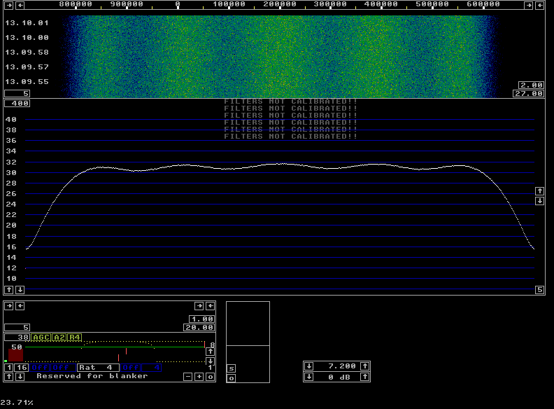
|
|
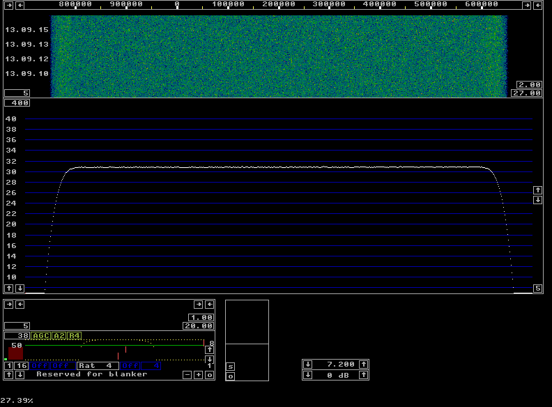
Just by making wse_dsp_corr available to Linrad without changing anything else, the screen changes and looks like this: |
|
|
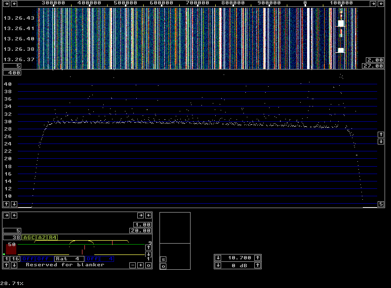
It is obvious that the gain of the colour scale could be increased drastically. (Use the F1 key to locate the appropriate controls.) This would allow search of extremely weak signals over the entire 1 MHz bandwidth if the waterfall averaging were increased to keep the random variations small. This might be of interest on microwave bands. On VHF and lower this aspect is not so interesting, the following image shows what the output of my RX70 looks like when it is routed to the Perseus rather than to the WSE10700. |
|
|
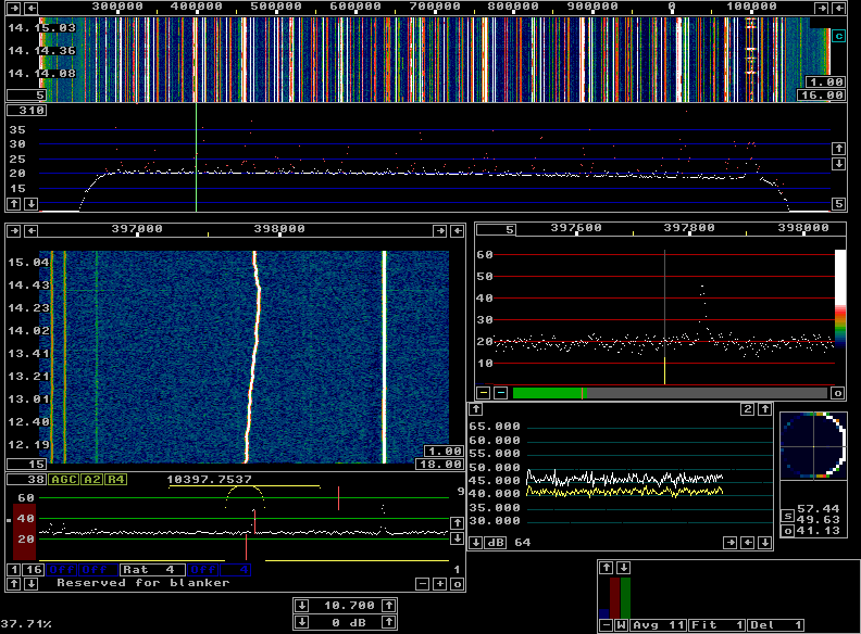
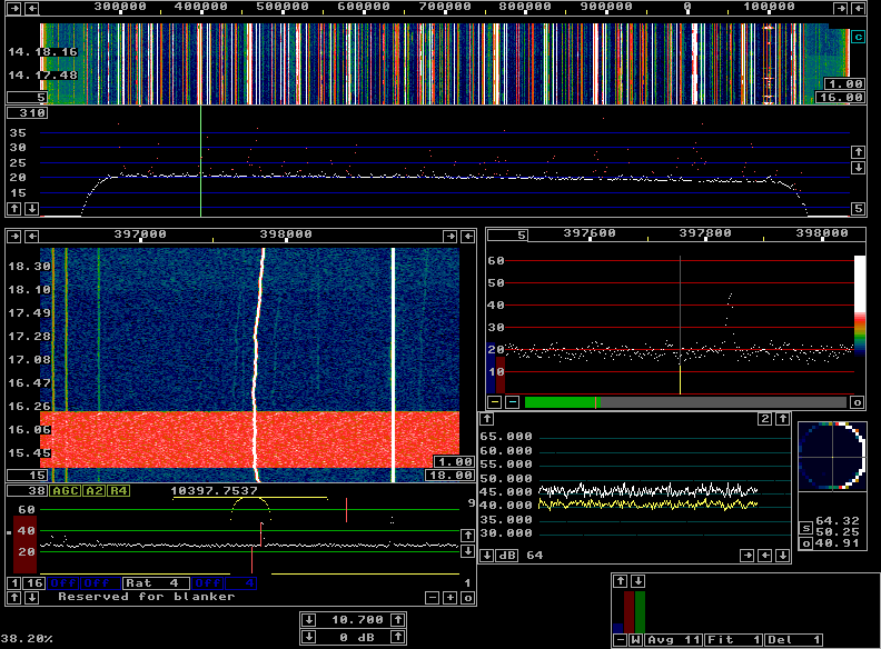
A better visibility for weak signals would increase the number of visible spurs and make the screen useless for finding interesting signals. The spectrum is approximately from 144.0 to 144.8 MHz and the signal at the right hand side is a local packet node. The gain differs by about 2 dB from 144 to 144.8 MHz. This will have a small effect on the noise blanker, but it will be very hard to detect under normal circumstances. The proper procedure would be to re-calibrate with a pulse source at the 144 MHz antenna input. To demonstrate the way the blanker works, a 20 dB directional coupler was inserted between the antenna and the preamplifier. A 300 Hz pulse generator was connected to the directional coupler to inject a signal level that would rise the RMS noise floor by about 13 dB. The following four images are saved in sequence and show what the screen looks like when the noise pulses and the blankers are switched on and off in various combinations. The first screen below is the antenna signal without any pulses from the pulse generator and with the blankers off. There are two pulses visible in the 3 minute period at 14.13.40 and 14.14.35 in the baseband waterfall. |
|
|
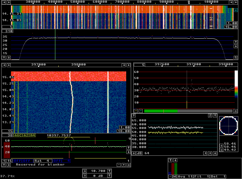
The second screen shows the noise floor going from blue to red when the pulse generator is switched in. The main spectrum shows an increased noise level by about 13 dB while the S-meter reading is increased by 10 dB only since the signal (spur) that is being received has S/N close to 1 when the pulses are not present. |
|
|
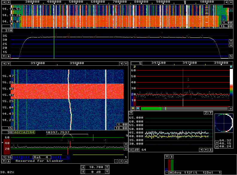
The third screen in this sequence shows what happens when the blankers are switched on while the pulse generator is running. |
|
|
The noise floors in the waterfall graphs is back at their normal levels, actually a tiny bit below, but the main spectrum is still 13 dB above normal showing clearly that the pulses are still present. The last figure (below) in this sequence of four shows what happens when the the pulse generator and then the blankers are switched off. The time when the pulser is switched off is invisible, but the time when the blankers are switched off shows a small increase in the noise floor. There is always a small contribution from powerline QRM to the noise floor at my location. |
|
|
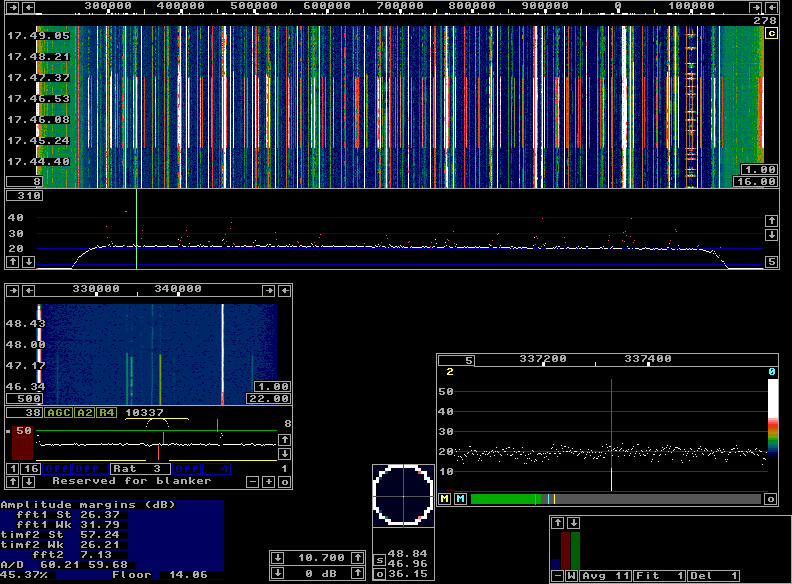
Using the noise blanker at 1 MHz bandwidth requires a fast computer. Both the first and the second FFT are in the same thread and when this thread is running 100% of the time Linrad will not work properly. On a dual core computer the CPU load may be 50% only because other tasks than the wideband FFTs use very little resources. The load is 50% on each CPU in a dual core machine, but since both of them process the same thread, CPU load could still be the limiting factor. It is possible to use MMX (multimedia) instructions to run the second FFT with only 16 bit accuracy. This is necessary on a 2 GHz Centrino Duo if a large size is desired for the second FFT. Follow the links at Linrad Home Page for a full description about the Linrad setup. The Perseus HF receiver is the fastest hardware currently available for use with Linrad (July 2008, Linrad-02.49) and therefore it is used as an example on this page. The figure below shows the screen with full processing of the 10.7 MHz output of the RX70 converter with 144.4 as the center frequency. |
|
|
The CPU load is 45% which means that Linrad uses about 90% of the available resources for the wideband FFTs. The spur removal is enabled and at the moment of the screen dump, 278 notch filters were applied to remove 278 different spurs. Between 17.45 and 17.47.30 the spur removal was disabled. The baseband waterfall shows how several spurs disappear while one is unaffected. The notches have a bandwidth of about 1 Hz and spurs that are wider than that are not removed. The parameters used for the wideband processing on 144 MHz can be downloaded here: pers144all.zip The same information from the parameter select routine is shown below. |


|
|
Note that the size of the second FFT is 524288 and that such transforms are computed four times per second to provide a bin bandwidth of 3.8 Hz at a complex sampling speed of 1 MHz wit 50% overlapping transforms. More functions.This page is just an introduction to newcomers. It is only intended to assist in the first attempts to get Linrad running. For information about baseband processing and how to use the transmit side including the radar function, follow the links at Linrad Home PageTo SM 5 BSZ Main Page |