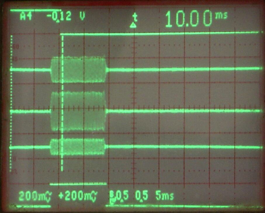
Fundamental aspectsThe gain of the transmitter has to be turned down in the receive period, at least for high power VHF transmitters because the isolation of the Rx/Tx switch would not be high enough to suppress the white noise floor. The white noise floor might be between -140 dBc/Hz and -155 dBc/Hz so at a peak power output of 1500W (+62 dBm), the noise floor at the transmitter output would be between -78 and -93 dBm/Hz. The antenna noise floor (at VHF) is -174 dBm/Hz and we would like to have the noise from the transmit side something like 20 dB below that to not loose 0.1 dB on the system noise figure. That means that the Rx/Tx switch has to isolate by 100 to 120 dB which could be difficult at VHF frequencies.It is a good idea to turn the transmit amplifiers off completely during receive periods because there is always a risk for unexpected behaviour of computers and all hardware should be completely safe against software errors. The time to switch the grids on big vacuum tube amplifiers could be a couple of hundred microseconds. There are fairly big decoupling capacitors that have to be charged or discharged. The control voltage for gain control will have to be changed something like 0.3 ms before the start of the keying waveform and the ability for the power amplifier to produce power will not have disappeared until 0.3 ms after the end of the keying waveform. The precise timing needed can not be obtained by writing to the parallel port or some other digital output (as far as I know). The delay through the soundcard device driver is not known accurately enough and it is also difficult to change the state of a digital output on a PC computer within 100 microseconds of a desired time even if the soundcard device driver could tell us precisely how many samples the buffer contains. Fortunately there is an easy way around the PC real-time limitations. The transmit signal, I and Q from the soundcard, can be used to send a pilot tone on the Nyquist frequency. The transmit chain can detect the pilot tone while blocking it so it does not cause a spur in the emitted signal. The output from the detector can then be used as the input of a sequencer that makes sure that PIN-diodes or relays are in the transmit position before power amplifiers are turned on. A full scale transient on the soundcard output will be detected as if it were the pilot tone and the TX2500 will generate a full level signal. The sequencer will assure that Rx/Tx switching and PIN-diode or relays are operated in a safe order in all cases. The worst case error would be that the transmitter emits wideband interference to other band users. The pilot tone detector in the TX2500.The Delta44 has a noise floor on the output side that is compatible with the dynamic range of the input side. the baseband dynamic range of the Delta 44The noise floor is about 108 dB below the full carrier level in 2.4 kHz bandwidth. Based on that one would like to place the pilot tone at -85 dB relative to full power to detect it with an S/N of 20 dB in a bandwidth of about 5 kHz. The detector does not need selectivity against the I/Q transmit signal because the pilot tone is always present when something is (intendedly) transmitted. Figures 1 to 6 show oscilloscope traces of I, Q and I-Q in the TX2500. Linrad is set to transmit on 144.060 and the frequency of I and Q is 35 kHz. The key-down time is set to 10 ms and the duty to about 10%. The upper trace is the keying signal. The lowest trace is the control signal that is produced by the RX2500 hardware that has a detector that senses the amplitude of middle trace which is (I-Q). The remaining traces are I and Q respectively. The pilot tone at 48 kHz is suppressed by a series LC notch circuit to ground in both I and Q. The signals in figure 1 are picked up by secondary windings on the notch inductances and amplified. The signal level is set to -90 dB and it is further attenuated by the series LC filters which are notches at the Nyquist frequency for the transmitted signal but work as band pass filters filter for the pilot tone detection. The signal itself, 35 kHz is not visible in figures 1 to 6. They just show the sync tone abd the sync tone detector output at different levels and number of bits sent to the soundcard. |
|
|
|
Fig 1. Pilot tone -80dB, 16 bit data. |
|
|
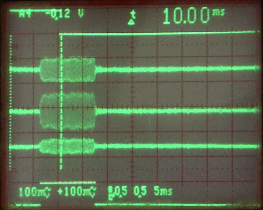
Fig 2. Pilot tone -85dB, 16 bit data. |

|
|
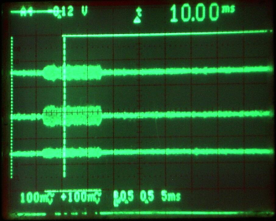
Fig 3. Pilot tone -90dB, 16 bit data. |

|
|
Fig 4. Pilot tone -90dB, 32 bit data. |
|
|
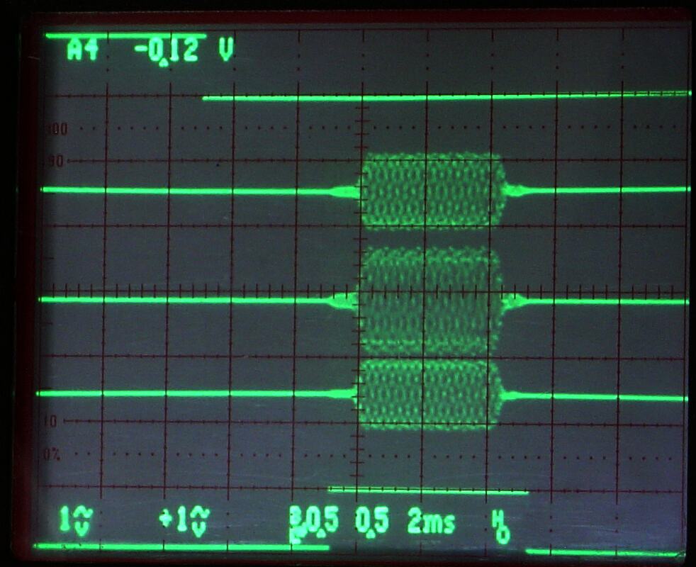
Fig 5. Pilot tone -95dB, 32 bit data. The pilot tone detector works ok down to -85 dB with 16 bit data sent to the Delta44 but when the tone is set to -90dB the control signal is no longer reliable this can be seen in figures 1 to 3. When 32 bit data is used for the Delta 44, the control signal is ok at -90 dB but it is not reliable at -95 dB. Figures 1 to 5 show that a setting of the pilot tone at -80 dB will be adequate and provide a good safety margin when 32 bit data is used for the Delta 44. Figures 1 to 5 are made with a rise time of 1 ms, the minimum rise time that Linrad allows. Figure 6 shows the same measurement as figures 1 to 5 but with the signal set to -40dB. The pilot tone is about 180mV p-p when set to -80 dB as can be seen in figure 1. The pilot tone is 180 degrees out of phase between I and Q so it shows the summed amplitude in the center trace which is I-Q. Figure 6 shows that a signal set to -40 dB is at 1.1V which means that a signal set to about -56 dB would have the same amplitude as the pilot tone when set to -80 dB. The bandpass filter which is used to recover the pilot tone thus suppresses the signal by about 24 dB for a signal frequency of 35 kHz. |
|
|
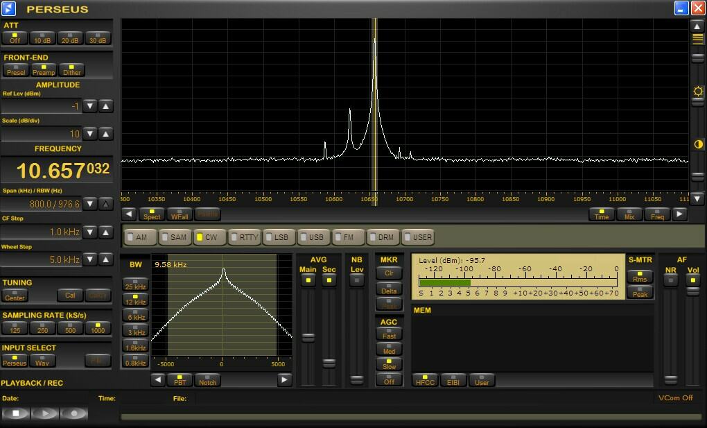
Fig 6. Signal level -40dB. The test points are the same as for figures 1 to 5. The emitted spectrum.The rise and fall time of 1 ms will generate keying clicks ofer a frequency range in the order of e/t on both sides. This means that the keying clicks will have a bandwidth that approaches the bandwidth of an SSB signal. Such a short time constant should be used only when needed, for example for radar observations of aurora and other ionospheric phenomena.Compared to what is normal on the amateur bands, the keying clicks at a rise time of 1 ms are modest. Figure 7 shows what they look like on a Perseus HF receiver with the perseus.exe software. The signal is about 1 dB below A/D saturation and it is taken at the output of a WSE RX70 at 10.7 MHz. The keying is 5 ms key-down and 20 ms key-up for a 20% duty cycle. |
|
|
Fig 7. The Linrad Tx as seen with a Perseus using its own software. Figure 8 shows exactly the same thing as figure 7, but here the software used is Linrad. |
|
|
Fig 8 The Linrad Tx as seen with a Perseus using the Linrad software. Both figure 7 and figure 8 show the spurs generated by the TX2500. The main signal is at 10.657 MHz. The signal at 10.630 is the LO leakage. It is clear from figure 8 that this signal does not have the nice shaped rises and falls of the main signal. The LO leakage signal is abruptly keyed by the control signal. |
|
|
Fig 9 The LO leakage is abruptly keyed by the control signal, the bottom trace of figures 1 to 6. Figure 10 shows the Linrad Tx signal as seen with the WSE converters and figure 11 shows the same time span as seen with a Perseus using the same 10.7 MHz signal which is fed into the RX10700. |
|
|
Fig 10 The WSE converters are here used to show the Linrad tx spectrum at 1 ms rise time. |
|
|
Fig 11 The Perseus HF receiver used to show the Linrad tx spectrum at 1 ms rise time. Linrad (June 2008) is not yet mature on the Tx side. Occasionally there are glitches, underruns on the tx output side. Two such events can be seen in figures 10 and 11. Glitches are a severe threat to the receiver frontend and to the PIN diode switches because the pilot tone disappears suring an underrun and when output resumes, the signal is immediately at full power level. In case the signal loss is more than a few tenths of a millisecond, the control signal will disappear and then after only maybe 100 microseconds, the PIN diode will be in its off state. If full power would be applied abruptly then, the PIN diode and the Rx front end would explode. There is a need for some safety circuitry. Even when the Linrad software runs properly, there is a risk that some other program stops the output for a while. The transmitter hardware must ensure that computer errors does not cause damage. Both figures 10 and 11 have a 15 kHz filter in the baseband which allows a direct comparison of the S-meter graphs. The key-down power level is set to S9+50 dB in both figures and one can see that the Perseus noise floor is about 2 dB lower than the WSE noise floor. For signals within the visible window of the WSE system, the Perseus HF receiver thus has a 2 dB larger separation between the point of saturation and the noise floor. For signals outside the visible window, the WSE converters have about 20 dB more dynamic range than the Perseus HF receiver. To SM 5 BSZ Main Page |