linrad support: RF amplifier and filter for 10.7 MHz
(April 22 2004)

The RF amplifier

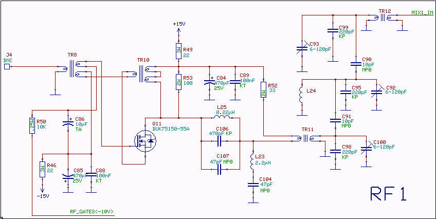
The RF amplifier is similar to the one used in the 2.5MHz amplifier. At a frequency of 10MHz the capacitances of a power MOS-FET become significant. Noiseless feedback by the use of transformers is no longer straightforward. Intermodulation and overtones are caused by the variation of the capacitances with the voltage. Performance is adequate if a MOS-FET with high enough channel resistance is selected (with associated small capacitances).

The input IP3 of the RF amplifier is in the order of +45dBm which is high enough to make the 10.7 to 2.5MHz converter dominated by IM3 from the mixer. The entire unit has an input IP3 of about +40dBm.

The gate transformer, TR8, is wound on a ferrite toroid core from Ferroxcube (Philips). Material 4C65, type TN 14/9/5. The gate winding is 6 turns, the source winding is 3 turns and the input winding is 7 turns. The wire dimension is uncritical.

The drain transformer, TR10, is wound on a ferrite toroid core from Ferroxcube (Philips). Material 4C65, type TN 14/9/5. The winding is 6 turns with three twisted wires. The wire dimension is uncritical.


Fig.1. Circuit diagram for the 10.7 MHz RF amplifier and filter.

The 10.7 MHz band pass filter

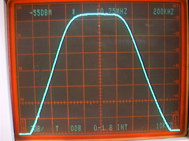
The 10.7MHz band pass filter has a flat response over about 500 kHz. The frequency response is shown in figures 2 and 3. The main purpose of the 10.7MHz filter is to suppress the mirror image 2.5 MHz above the local oscillator. Since the mixer is sensitive at harmonics of the local oscillator, higher frequencies also have to be well suppressed.

The mirror frequency (15.7MHz) is suppressed by more than 80dB. There is a notch filter at this frequency, without the notch the mirror frequency would have been attenuated only by about 65dB. The notch is made with low cost standard inductors. They form resonators at 15MHz so they do not produce third order intermodulation problems for strong signals at 10.7MHz.

The 10.7MHz receiver is intended as an IF unit. The unit in front of it is responsible for suppressing signals at the undesired responses of the 10.7MHz unit. Undesired responses several MHz away from the desired passband will easily be suppressed by an additional 40dB to provide a mirror image rejection in excess of 120dB.

Feeding very strong signals at 13.2 and 15.7 simultaneously to the unit may give third order intermodulation products within the desired passband due to the non-linearities of the 2.2 microhenry inductor in the notch filter. This is another reason why stages in front of the 10.7 MHz unit should suppress 15MHz by at least 40dB.

The 10.7 MHz bandpass filter uses T80-6 toroid cores from Amidon. The resonant winding is 12 turns of 0.8 mm enameld wire on all three cores, TR11, L24 and TR12. The input winding on TR11 as well as the output winding on TR12 is 4 turns of 0.5 mm wire.


Fig.2. Frequency response of RF filter. Vertical is 3dB per division and horisontal is 200kHz per division.


Fig.3. Frequency response of RF filter. Vertical is 10dB per division and horisontal is 2MHz per division.


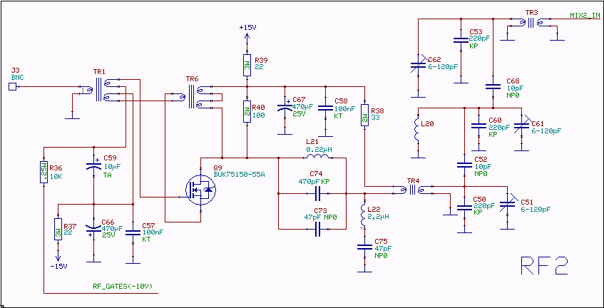
Fig.4. The second channel differs only in component numbering.