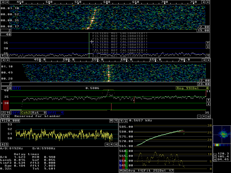
Fig. 1. A CW signal in SSB bandwidth received by Linrad on an uncalibrated system. The time delay is about 8.5 seconds, when listening to a live signal from the soundcard the delay caused by the D/A buffer can be set very small.
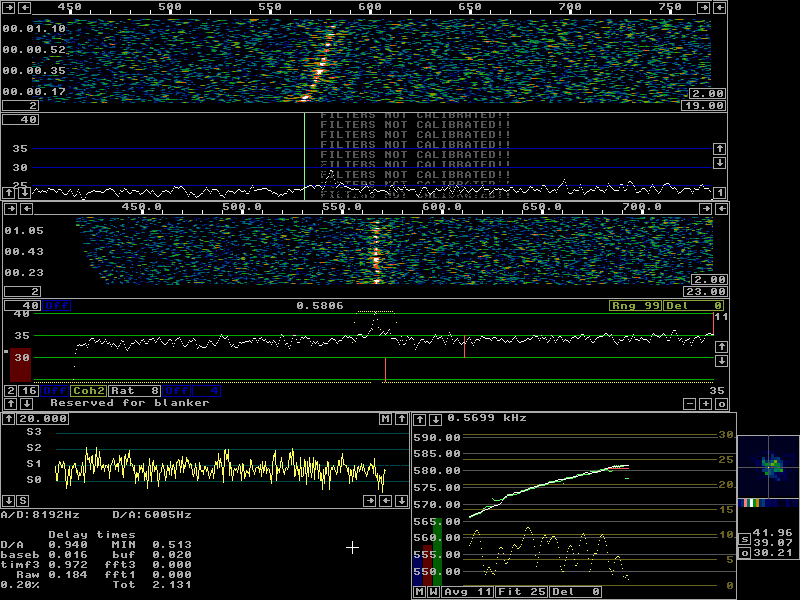
Spectrum display and audio filter with AFCWhen using a normal SSB receiver at VHF/UHF frequencies the builtin noise blanker of the SSB radio usually works well. Problems with strong signals within the passband used by the noise blanker are not as much of a problem as on more crowded bands.The noise blanker within linrad can be used to improve in case the analog blanker fails. To use the linrad blanker, the system has to be calibrated by use of a pulse generator. In normal operation with a good receiver having a reasonably flat frequency response calibration is not required As an illustration to the practical use of linrad for a single polarised antenna with a conventional SSB receiver fig. 1 shows the reception of the UNKN422.WAV file. The parameters are set for high performance in copying really difficult signals. The time delay is about 8.5 seconds from input to audio in the headphones, but nothing prevents the transmitter to start while the last part of the received signal is still being processed. The delay is primarily caused by the AFC which is set to interpolate and compute the optimum frequency based on the spectrum 7 seconds back in time as well as 7 seconds into the future. Figure 2 shows the screen when the AFC is set to extrapolate by fitting a straight line to the spectrum 14 seconds back in time. |

Fig. 1. A CW signal in SSB bandwidth received by Linrad on an uncalibrated system. The time delay is about 8.5 seconds, when listening to a live signal from the soundcard the delay caused by the D/A buffer can be set very small. |

Fig. 2. Here the delay is reduced to less than two seconds by allowing the AFC to use an extrapolated value. |
In figures 1 and 2 the main waterfall and the baseband
waterfall are set to have the same parameters so one can
directly see how the AFC affects the spectrum.
It is obvious that the quality of this signal is good
enough to allow operation with a small time delay.
As can be seen from the AFC graph the frequency error
is about 1 Hz for a while when extrapolation is used.
This is the error caused by extrapolating across the
first region of no signal in the first fadeout.
When the AFC uses interpolation, the error is much smaller.
Having to open the baseband filter by 2 Hz to accomodate for
some frequency error might be a good price to pay
for the much shorter processing delay.
Setup parametersThe figures 3 to 5 below show the parameters that were used to produce figures 1 and 2. |

Fig. 3. Parameters for the first fft. Note that the low value of First FFT amplitude is because the input is a 8 bit .WAV file with a high signal level. Since the noiseblanker is not needed the second fft is deselected. |

Fig. 4. AFC is enabled. |

Fig. 5. These are the default AFC parameters. |

Fig. 6. The unkn422.wav file is recorded at 8192 Hz in real format (one data value per sample). The conversion to complex (analytic) format represents the same data at a sampling speed of 4096 Hz (two values, I and Q, for each sample) The baseband sampling speed is 2048 Hz. The default output mode is coherent processing. It is necessary to use stereo head-phones when listening because the decoding is done in the brains of the operator and the phase information between the two ears will help a little. |
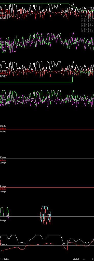
Phase stability of the EME signalWith the parameters of figure 1 the waveforms produced by the coherent processing are shown in figure 7. This is an output of the experimental routines that some day may become the CW decoding algorithms of Linrad.The first level "Raw" shows amplitude and phase of the signal that passes the baseband filter with a bandwidth of about 20Hz. The second level, also "Raw" shows the same signal in complex format I and Q. The bottom level, "Carr" shows the signal that passes through a filter that is about 2.5 Hz wide. (The Coh parameter 8 times narrower than 20Hz) It is obvious from the carrier track that the phase is stable over several seconds during the initial QSB peak. The signal sent to the earphones, "Coh1" is obtained by shifting the "Raw" signal by the phase angle determined from the "Carr" signal. It is displayed both as phase and amplitude. In Coh2 mode, the complex signal is sent to the ear-phones after being shifted from zero frequency to the frequency selected with the BFO control. I to one ear and Q to the other ear. When the Coh1 mode is selected, the "Raw" signal is sent to one ear and the "Carr" signal to the other while the in-phase signal, the green curve of the fourth level is sent to both ears when the Coh3 mode is selected. Note that the relative phase between the two ears is reversed if you select one channel only for the output and that this will degrade performance if you use loudspeakers rather than head-phones. |

Fig. 7. The signals passing the baseband filter when UNKN422.WAV is processed like in figure 1. This is the very beginning of the recording. To SM 5 BSZ Main Page |