Making the PC computer quiet at 144MHz.
(Sept 22 2003)
|
Putting the PC in a box
The PC radiates not only from the wires going to the box.
There is radiation from the hard disk and possibly also
from wires under the plastic front cover.
The box itself also radiates due to insufficient electrical
contact between the different parts.
Rather than trying to screen at many points and to add a lot
of screws to improve electrical contact it is much more
convenient to place the entire computer inside a metal box.
Fig. 1. shows the box inside which the PC is running.
Cooling is important.
Note that there is a hole which leads the warm output
air from the PC fan to the outside via a chimney.
There are holes in the outer box at the same place where the PC
gets its cold air.
|
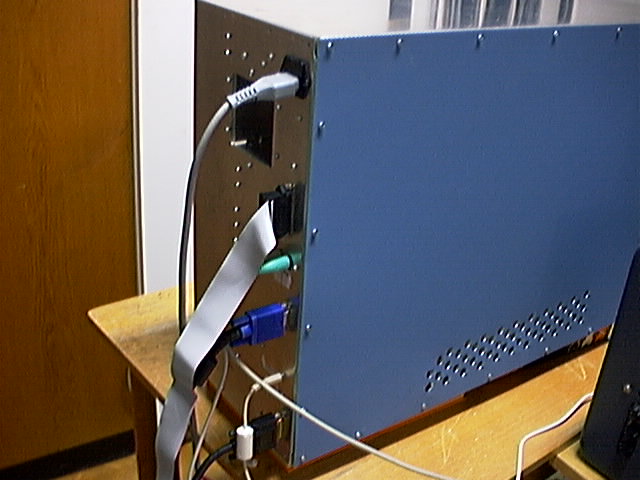
Fig. 1.
The complete box with the PC inside.
Note the holes for cooling.
The temperature of the air coming out from the box is 32C at an ambient
temperature of 22C.
This is probably low enough to make the PC last until it is obsolete.
An extra fan could be added on the box at the air outlet in case the
temperature is too high.
Filtering the mains power
There are standard RFI filters that are built into a standard
mains socket.
None of these that I have tested has adequate attenuation at 144MHz.
For good attenuation at HF as well as VHF a pi filter is placed at the
mains input socket as shown in figures 2 and 3.
|
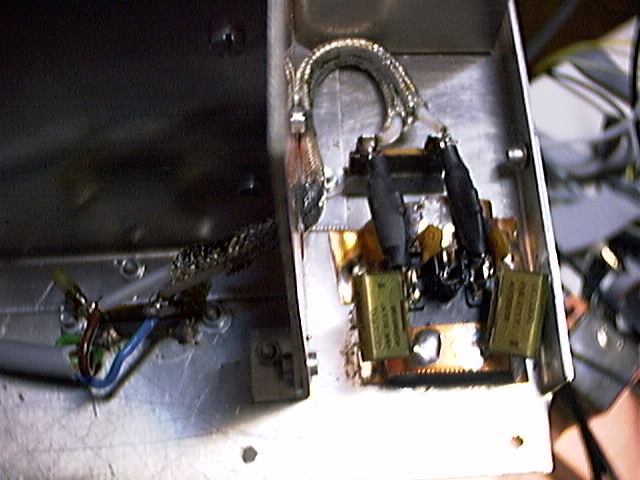
Fig. 2.
The mains filter. See text.
Standard capacitors for mains decoupling, 68000pF
metallised paper, are connected to ground right at the 220V entry.
Note that this capacitor value is too large according to safety rules.
The impedance is 50 kiloohms so the current to ground will be 4 mA !!
This kind of EMI protection is safe only if you make sure that the box
is always permanently connected to protective ground.
If there is any risk that you or someone else may operate the PC inside the
box when the box is not installed as a part of your radio station and
properly grounded, make the total capacitance less than 2200 pF.
The 68 nF capacitors have a rather high inductance so there are also
1kV 470pF ceramic capacitors in parallel.
The 470 pF capacitors have a series resonance at 144MHz if
the wires are made short.
This capacitor form a parallel resonator with the inductance of the
68000pF capacitor so attenuation is not very good at 70MHz.
The 1kV ceramic capacitors may not have the quality required according
to safety requlations.
It is safe if your box is guaranteed to always be connected
protective ground.
If there is any risk that the box is removed from your radio station
and operated by someone else, make sure to follow all safety regulations.
|
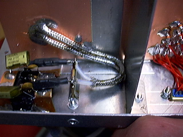
Fig. 3.
Detail of mains filter.
Two inductors 100uH with 3.3 kiloohms in parallel with each
are connected to the decoupled mains input.
The capacitors to ground that are needed to complete the pi filter
is placed at the other side of a screening wall, placing them
close to the mains input socket gives poor isolation at 144MHz
because it would be too near to the grounding point of the input
capacitors.
Some teflon insulated coaxial cable is used to connect the inductors to
the output capacitors which are very hard to see in the image.
The output capacitors are 470pF.
At 144MHz the attenuation is above 80dB.
The parallel port
Linrad uses the parallel port for slow speed communication
with the hardware.
All wires are filtered with feed-through low pass filters that
give very high attenuation.
The feed through filters are soldered into a copper laminate
that is well connected to the back wall.
Fig. 4 shows an overwiev and fig. 5 gives details for the parallel
port filtering.
|
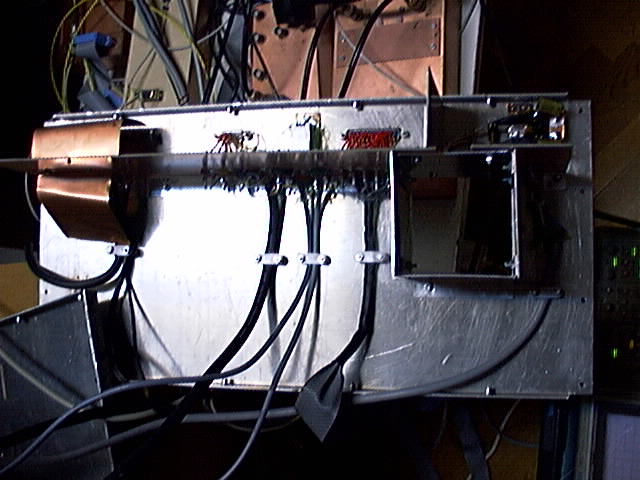
Fig. 4.
The inside of the back wall of the box.
There is a 8cm high copper laminate perpendicular to the
aluminium that constitutes the wall of the box.
Filters are placed in this laminate.
Cables with interference enter from below in the figure
and the filtered wires are connected to the appropriate
connectors above the laminate.
The laminate is well grounded to the aluminium at many points.
|
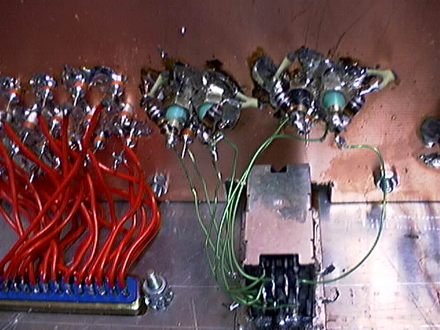
Fig. 5.
Filters for parallel port, mouse and keyboard.
Mouse and keyboard filters.
The PS2 mouse needs high speed communication and the feed through
filters can not be used for the data wires.
These wires are filtered by a series link to ground and a parallel
LC in series with each data wire 15pF and 0.1uH standard inductors
are used.
The series resonators to ground can be seen in fig. 5 and
the parallel resonators in fig. 6.
The 5V line to the mouse has a feed-through low pass filter.
The keyboard the same filters as the mouse.
|
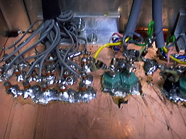
Fig. 6.
Parallel port filter and mouse filter, computer side.
Part of the keyboard filter is also visible.
Video filters.
There are filters in all wires to the screen.
This may well be unnecessary because all wires are contained
in a common screen.
I have put them there anyway so I know that whatever
interference coming from the screen is generated there.
The three video lines and the sync line have the same filters
as the mouse data lines while the control lines have
feed-through low pass filters.
Sound filters.
The loudspeaker outputs have feed-through low pass filters
while the sound input to the
modified Delta44
has five filters with resonators identical to the mouse control line
filters. One for each signal wire and one for signal ground.
Signal ground must not be connected to any ground point, it
is a voltage reference needed by the signal source and no current
should be allowed to flow in it.
Inside the box there is no outer screen around the four screened
analog input wires. The box itself is enough.
|
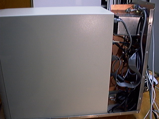
Fig. 7.
The computer side of the filters when the box is partly assembled
|
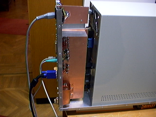
Fig. 8.
The exit side of the filters when the box is partly assembled
Screen and mouse
After the computer is placed inside the box, the dominating
interference source is the PS2 mouse.
Different brands behave very differently.
I have tried two different Microsoft mice and one Logitech.
The Logitech is much better than the Microsoft ones and after
wrapping some copper foil around the little PCB inside the mouse
it is acceptable. The foil is connected to the cable screen.
Mouse interference is very bad, it has high bandwidth - it seems
to originate in some unstable clock signal
inside the mouse.
Making a screen silent may be very difficult.
I am currently using a Samsung SyncMaster 570B tft screen which
produces some spurs but does not give any wideband noise.
|
�