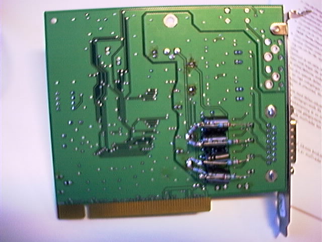
The Delta44 input circuitryThe input circuitry is an op-amp that provides a low pass filter. By replacing the input circuitry with a simple voltage divider the noise floor is lowered by 1dB. With proper filtering ahead of the Delta 44 the builtin filter is superflous and its noise contribution can be removed. It is a simple modification. Remove the capacitors C57, C59,C63,C65,C71,C73,C79 and C81. These capacitors are at the inputs and the outputs of the input amplifier/filter. Connect 6.8k resistors from the inputs through 2.2k resistors to analog ground to make voltage dividers that attenuate by the same amount as is done by the normal input circuitry. Then connect capacitors from the voltage dividers to the codec inputs. I have used 470 microfarads to extend the low frequency range but at the present time I do not know if that is any improvement over using the 10 microfarad capacitors that were used originally.This modification lowers the noise floor of the already modified Delta44 by one more dB. The components are conveniently placed on the solder side of the board as shown in fig.1. They may equally well be placed on the component side. Back to summary of Delta 44 modifications |

Fig. 1 The solder side of the modified Delta44 board.

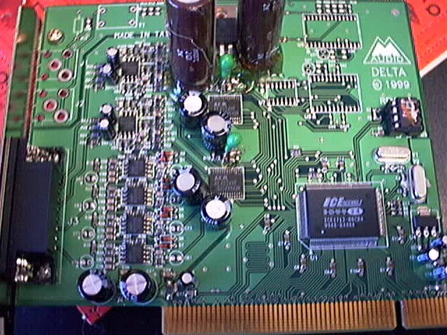
Fig. 2 The component side of the modified Delta44 board.
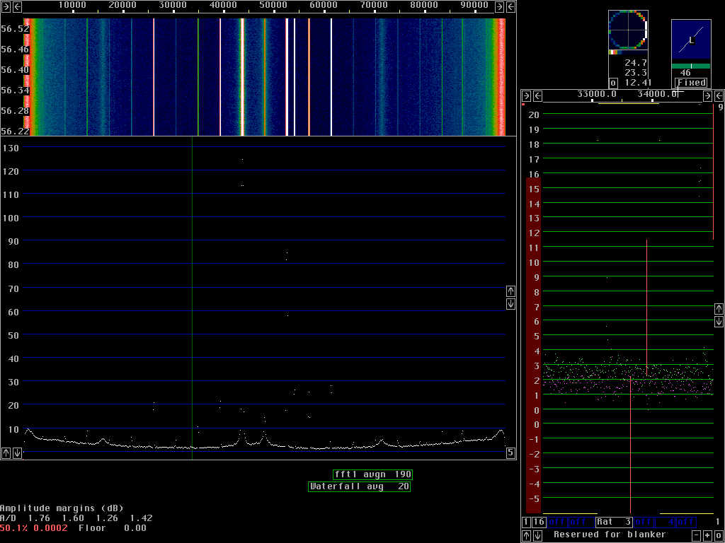
The spurs are as follows:
Freq   Level    Description
(kHz)  (dBc)
43.6     0      Main signal
52.4   -38.6    Mirror image (system uncalibrated)
61.3   -95.0    Audio, third harmonic.
56.8   -98.8    Audio, second harmonic.
39.2  -101.7    Audio, second harmonic.
25.9  -102.3    Audio, fifth harmonic.
48.0  -109.3    I and Q zero frequency 1/f noise etc.
34.8  -113.0    Audio, third harmonic.
16    -125      Sampling clock modulation?
71    -125      Sampling clock modulation?
The noisy spurs at 16 and 71 kHz originate in the Delta44. These spurs are slightly reduced by 10 microfarad capacitors on pin 23 (digital power supply) of the AK4524 codec chips. These are the green tantalum capacitors visible in fig. 2. Without these capacitors these spurs are 1dB stronger.
An interesting phenomenon is that the noisy spurs disappear completely if the output of U5 is shorted for a short time by connecting a discharged 1000 microfarad capacitor to ground. Nothing else is affected and these spurs do not come back until the device driver is stopped and started again. I have tried to increase several other decoupling capacitors but I have not found any way to reduce these spurs further.

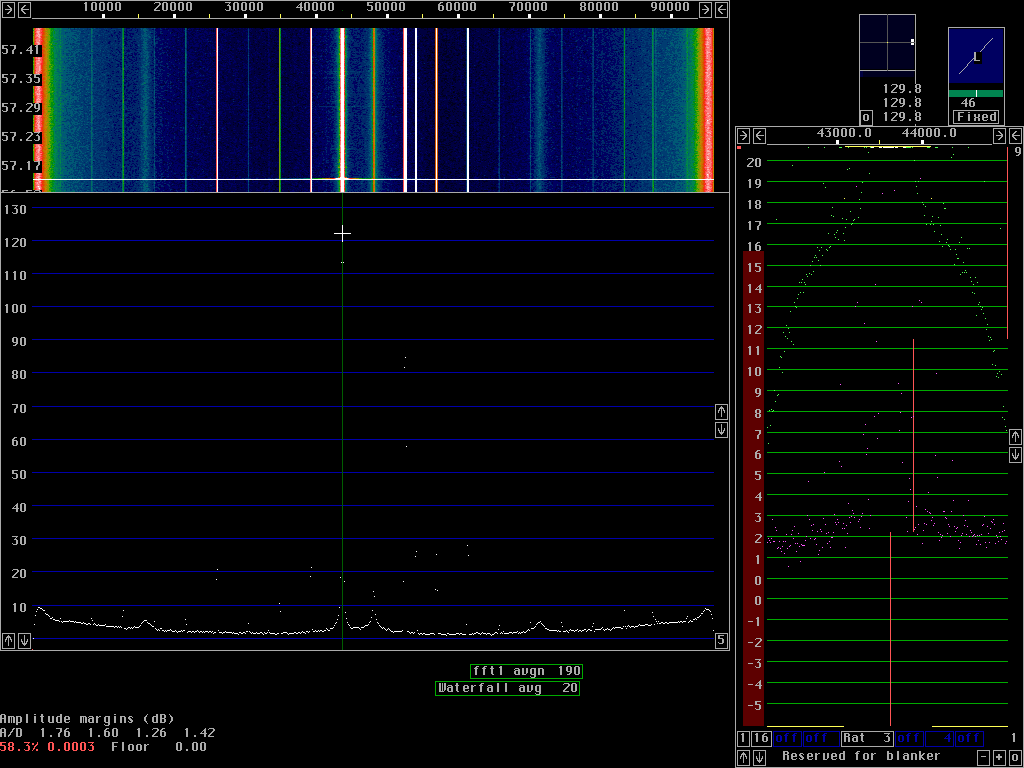
 Fig.4 Same as Fig. 3 but the cursor is moved to the strong signal
which is at 129.8dB.