LOW LEVEL EME
(Feb 23 2000)
On this page you can see some images showing the signal
transmitted by KK7KA, Stewart and received by me,
SM5BSZ, Leif via reflection off the moon.
The transmitted signal is a carrier of about 2 minutes duration
and it was received in stereo with 20kHz bandwidth and recorded
on a DAT recorder.
The transmit antenna was 10 elements on a 2.1wl boom (1/2 of a
2MXP20) with an estimated gain of approximately 12dBd.
The receive antenna was 4x14 X-yagi with 21.4dBd gain.
The rx cable loss was 0.15dB feeding MGF1425 preamplifiers
with low (but unknown) noise figure.
Stewart transmitted at randomly selected frequencies within a 2kHz
wide region. For each new (lower) power level Stewart changed
the frequency.
I could receive four power levels and sent a spectrum image with
the four frequency values to Stewart. In this way we could convince
ourselves that I had really received the transmissions.
Stewart (knowing where to look) could see five power levels as indicated
by his table below, verifying my frequency results.
13:14:45      350     144.166630          11726
13:17:15      200     144.167658          12744
13:19:30     ~130     144.168263          13338
13:22:00       50     144.168263              ?
13:24:08       50     144.167253          12295
13:26:15       25     [you guess]             ?
13:28:30       12     [I can't see this]      ?
13:31:15      350     144.167500          12498
The frequency resolutions in the graphs are in the order of 1Hz.
I do no longer remember the details. One limiting factor is frequency
stability.
By some better processing, using the known frequency drift -7Hz/min
(determined from the higher power levels) I was able to locate
the 25W transmission at 13025Hz using about 0.2Hz resolution.
I have not been able to find the 12W transmission.
The date of the experiment was Aug 8 1999. Both of us had elevation
high enough to eliminate ground reflections. The sky temperature
was 415K and the total degradation compared to best possible
EME conditions was 3.6dB
Under better conditions and with better frequency stability it would
be no problem to receive a 12W transmission.
If the combined antenna gain was evenly split our 21.4dB + 12dB
corresponds to 16.7dB at both ends which means that two
single yagi stations can communicate easily via EME using 12W output
power only if the boom length is about 8 wavelengths.
With 50W output power the minimum antenna size is 3.5 wavelengths
(13.7dBd) to achieve the results shown in the images below.
The data rate is limited to about 1 bit/minute using the most
unsophisticated modulation schemes.
With better frequency stability the threshold is probably
even lower.
The image below shows the whole transmission.

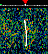
Below is the 350W transmission at 13:15 in a magnified scale.

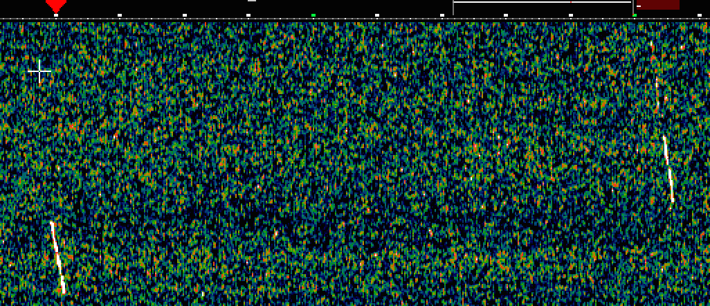
Below is the 200W transmission, close to the left edge of the spectrum.
The 130W and the first 50W transmissions are at the right side of the image.
The scale is magnified, each data point is 2x2 pixels.

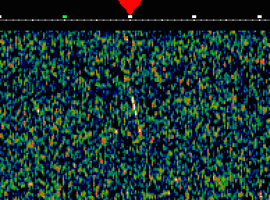
Below is the second 50W transmission
in a magnified scale.

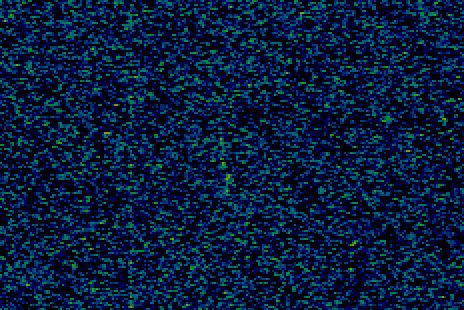
Below is the second 25W transmission
in a magnified scale and with higher frequency resolution.
This spectrum uses a constant frequency drift of -7Hz/min in the
digital processing to compensate for our lack of stability in
transmitters and receivers.


