|
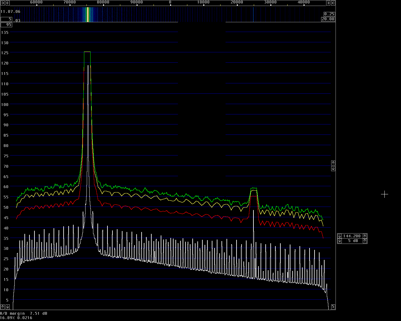
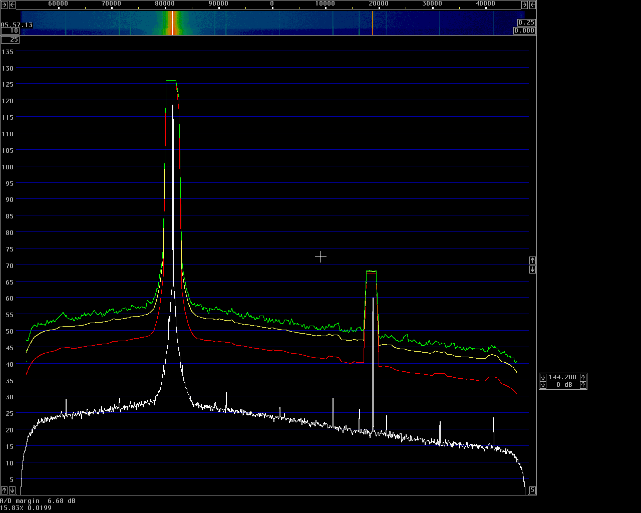
Fig.2 Carrier spectrum as in figure 1 when the FT-736R is
modified. The two VCC pins of Q26 qnd Q27 are cut and bent a little
upwards, connected to each other with a wire and to the +9V line
through a 47 ohm resistor.
A 47 æF capacitor to ground from the wire decouples the common VCC for
Q26 and Q27 and serves as the reservoar from which the current spikes
that the CMOS gates need can be taken without affecting the +9V supply.
(Without the resistor, a much larger capacitor is needed. 1000 æF reduces
the spurs by less than 6 dB)
|

