Aurora backscatter as indicator of conditions
When working DX in an aurora opening it may be difficult to know in what direction to point the antenna. If for example a station 700km south-west of my QTH is best heard when I have my antenna with azimuth 300 degrees, and gives only a weak signal when my antenna is at 30 degrees (with a small elevation), it may be much better to use 30 degrees because the reflection may be much stronger there when the other station turns his antenna.
Finding a good reflection point just by listening to the other stations may be misleading because it is not really telling where the really strong echoes are, it merely tells where the other guys heard each other.
By use of electronic switching between Rx and Tx, and fast keying, it is possible to use an amateur station as a radar. Looking at the amplitude of aurora backscatter is very informative. With some experience it is possible to decide very quickly where to point the antenna to attract the attention of DX stations when calling CQ.
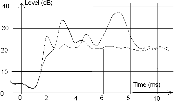
A simple amplitude vs time display gives the desired information directly. Figure 1 was recorded on February 12 1994 at 1400 UT with my old, medium power electronic relay which was built with two varicaps (MA4060). The power is about 500 W.
Figure 1 contains two curves. Both are with azimuth 10 degrees. One curve is with the antenna at the horizon, the other is with the antenna elevated 10 degrees.
The strongest echo is delayed by about 7.2 milliseconds, and it is about 1100 km away. This echo is seen only with the antenna at the horizon. In a good aurora it would be 20 dB stronger, but this level is enough to work medium sized stations who satisfy the geometrical conditions for this reflection point.
With the antenna at the horizon there are three more echoes. They are at about 1.7, 3.2 and 4.8 ms or at 250, 500 and 750 km distance. The reflection 750 km away is visible at 1200 km distance so it will allow communication up to about 500 km to the south. Aurora at a distance of 750 km comes in at about 5 degrees elevation, so it is natural to have this echo present also in the 10 degree elevation curve.
The echo 500 km away is very weak without elevation, but it is reasonably strong at 10 degrees of elevation. By reflections from this area it is possible to work good stations about 800 km south of my QTH.
The echo 250 km away is an aeroplane. Aeroplane scatter is quite common on 144MHz at distances around 500 km, aeroplane backscatter - the original radar concept - is of course nothing new ! Note that the aeroplane is seen only with the antenna pointed at the horizon, and that part of the aeroplane signal is muted at the end of the transmission pulse.
When the aurora echo is 40 dB above the noise at 2 ms time delay and 15 degrees of elevation it is possible to work stations 1000 km to the south. Such reflection points do not last long, usually only 5 minutes or so, and they vary in azimuth from about 330 to 30 degrees. When one is gone it is not uncommon to find a new one at a different azimuth.
The maximum echo level (so far) is 60 dB (500 W) with 15 degrees of elevation. Pointing the antenna north during such circumstances produces strong signals from a large area from 1300 km east or west to 1050 km to the south. Stations north to my QTH, or at only a few hundred kilometres distance are not so strong because they do not have elevated antennas. (But maybe in the future...)

Figure 1. Echoes from a relatively weak aurora event February 12 1994. the two curves are with 0 and 10 degrees elevation. See text above
FFT analysis of aurora echoes
The backscatter from the aurora is slightly doppler shifted. Of course it is much easier to determine the frequency shift by listening to some other station at a convenient distance. Then a continuos carrier can be used, and the true spectrum is obtained by use of a FFT with high resolution.If however the aurora comes from several reflection areas in the same direction, but at different distances, the spectrum from a continuos carrier will not give the spectra corresponding to the different reflection points, it will only give an average.
With a pulse length of about 2.5 milliseconds, the frequency resolution is about 200 Hz and the distance resolution about 200 km. It is possible to get quite nice pictures of the dopler shift and its variation by distance, azimuth and elevation.
Due to the sun spot minimum, good aurora events have not happened frequently since I built the equipment. I have not yet had the opportunity to record anything from a major aurora, and I do not yet know if the doppler shift information is useful for any purpose.
A few typical recordings are shown below they are all from an aurora event on February 25 1996.
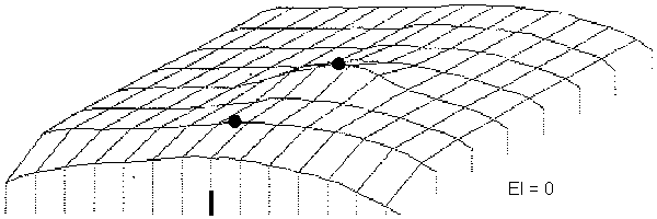
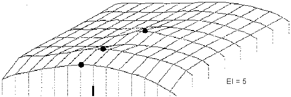
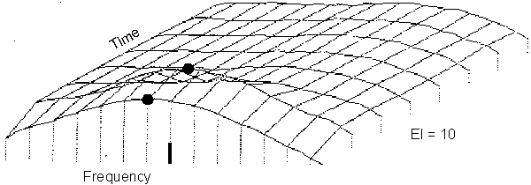
Fig 2 was recorded between 22.40 and 22.44 UT and it shows two reflection centres at azimuth 0. The distance can be seen as a time delay, but also as a difference in amplitude at different elevation angles. Fig 3 was recorded between 17.15 and 17.30 UT. It shows the typical behaviour of aurora backscatter. Echoes from north-east are shifted up in frequency while echoes from north-west are shifted downwards. It seems like the aurora is fixed in space (to the sun's magnetic field ?) while the earth is rotating. The shift is in the order of 300 Hz, corresponding to about 300 m/s or 1100 km/h, which is about the rotating speed of the earth at our latitudes.
The width of the doppler shift is much wider with the antenna north, but the peak is centred at zero shift. It seems like the random motion is mainly north to south. When the aurora is weaker, the doppler width is generally smaller, down to 50 Hz at the beginning or end of an aurora opening.
For aurora radar with high resolution in time, but (of course) no doppler information and no direction information, HLMS (Anchorage, Alaska) Real - Time Plots is an interesting site.


Figure 2 Echoes from a relatively weak aurora event February 25 1996 (22.40UT). The three graphs are with 0, 5 and 10 degrees elevation. The frequency span is about 3.5 kHz and the time per division is 1.9 ms (280 km). The frequency axis is inverted. The reflection at about 2 ms is about 300 Hz higher in frequency compared to the reflection at about 7 ms. The graph shows the average of many pulses in a logarithmic scale.


Figure 3 Echoes from a relatively weak aurora event February 25 1996 (1715 UT). The six graphs are with zero elevation and azimuth in steps of 20 degrees. The frequency span is about 3.5 kHZ and the time per division is 1.9 ms (280 km). The frequency axes is inverted. The reflection at about 2 ms is about 300 Hz higher in frequency compared to the reflection at about 7 ms. The graph shows the average of many pulses in a logarithmic scale.
Other echoes than aurora
During the summer I sometimes work random contacts via sporadic meteors using normal hand keying. This is when trying to work IONO scatter has failed. I have called CQ for IONO scatter, and hear sporadic pings from some station that is too weak to produce any IONO scatter signal. When I hear the reflections from a good (long lasting) meteor while I am transmitting, I sometimes send BK, deliberately deviating from the one minute sequence. On a few occasions the station at the other end was alert enough so we could finish QSO within a few seconds still using the same meteor.About 20 years ago I tried a SSB radar intended for meteor scatter. It was simply a unit cutting holes at suitable points in the SSB signal during about 20% of the time, turning on the receiver. Reports were that it sounded "very unusual" but not difficult to copy. With this system I had full break in on SSB and could even hear meteor reflections from myself while talking on SSB.
The real reason for the FFT addition to the 144MHz radar was not to investigate aurora or meteor trail reflections. I am waiting for a good sporadic E opening, and it would also be interesting to look for ground reflections in a good tropo opening. The sensitivity is reasonably good, figure 4 shows a typical EME recording. Like the other FFT recordings above, the graph shows the average of many measurements in a logarithmic scale.
 Figure 4 Echoes from the moon 24 mars 1996.
The figure shows the average of a large number of pulses in
a logarithmic scale The scale is expanded as compared to
the aurora graphs.
The wideband noise at the front is due to malfunction in the noise blankers
short after the transmission.
 Figure 5. The same data as in figure 4, but in linear power scale
The moon echoes give an average (S+N)/N of 1.35 in linear power scale as can be seen in figure 5. The post detector S/N is 0.35 and the S/N before the detector is something like 0.6. The bandwidth is about 10 times larger than the bandwidth I use for EME, so in normal bandwidth the S/N would have been 6 corresponding to 8dB. The optimum echo is about 4dB stronger. At this occasion faraday rotation created about 2dB loss, and the path loss another 2dB. When using the pin diode switch the noise figure of the receiver is degraded by 50 meters of cable, and the transmit and receive polarisations are always the same so faraday rotation is a problem.
To SM 5 BSZ Main Page