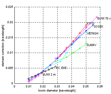
Boom corrections have been published by many authors. There is a distinct advantage in using isolated elements mounted through the boom tube so this mounting is most popular among amateurs. Elements in contact with the boom tube requires very good electrical contact since the currents are very high and a fraction of an ohm will cause significant ohmic losses. An insulated element is much less affected by the boom tube because there is a substantial magnetic field inside the boom tube that makes the inductance change much smaller. For these reasons we only give information about through hole insulated elements here on our amateur radio technical site.
For commercial/professional products we use elements in contact with the boom (welded) but the details is our company secret.
Figure 1 below shows the boom corrections currently in use among radio amateurs for through the boom insulated elements.
For comparison we have added a curve produced with
BC.EXE
This curve is for a 5 mm diamater element of length 900 mm mounted
through a 7 mm hole on a boom, ranging from 20 to 60 mm. The
wall thickness is proportional to the boom tube diameter and
ranges from 1 to 3 mm.

Fig 1 Currently used boom corrections.
Tables scaled from cm to wavelengths so 70cm
and 2m data will go into the same figure.
Note the error on 1" for DJ9BV 70cm 23.62
1. BOOM CORRECTION FOR THROUGH THE BOOM INSULATED ELEMENTS ON
   2 METERS & 70CM.

   PROVEN ACCURATE FOR BOOM DIAMETERS SMALLER THAN .055 WAVELENGTHS.
   MEASUREMENTS BY DL6WU.FORMULA BY G3SEK.

   FORMULA: C = 12.5975B - 114.5B^2
            C = CORRECTION FACTOR AS A FRACTION OF THE BOOM DIA.
            B = BOOM DIA IN WAVELENGTHS
            B^2 MEANS B SQUARED

   2 METERS
   BOOM DIAMETER           CORRECTION               ADD
   2 METERS.
   0.750" OR 19.050MM        10.56%          .0792" OR  2.01MM
   0.875" OR 22.225MM        12.10%          .1058" 0R  2.69MM
   1.000" OR 25.400MM        13.66%          .1366" OR  3.47MM
   1.125  OR 28.575MM        15.12%          .1701" OR  4.32MM
   1.250" OR 31.750MM        16.54%          .2070" OR  5.25MM
   1.500" OR 38.100MM        19.21%          .2881" OR  7.31MM
   1.750" OR 44.450MM        21.67%          .3792  02  9.63MM
   2.000" OR 50.800MM        23.91%          .4782" OR 12.15MM
             20.000MM        11.04%                     2.21MM
             38.000MM        19.17%                     7.28MM

   70 CENTIMETERS.

   DJ9BV USES THE FOLLOWING CORRECTION ON 70CM:
   0.787" OR 20.000MM        25.00%          .1968" OR  5.00MM
   1.000" OR 25.400MM        20.00%          .2362" OR  6.00MM
   1.125" OR 28.575MM        24.50%          .2756" OR  7.00MM
   1.250" OR 31.750MM        25.20%          .3149" OR  8.00MM
   1.375" OR 34.925MM        25.77%          .3543" OR  9.00MM

   K1FO USES THE FOLLOWING CORRECTION ON 70CM:
   0.875" OR 22.225MM                               OR  6.44MM
   1.000" OR 25.400MM                               OR  8.12MM
   1.125" OR 28.575MM                               OR  9.57MM
   1.250" OR 31.750MM                               OR 11.43MM
   1.375" OR 34.925MM                               OR 13.27MM

   VE7BQH USES THE FOLLOWING CORRECTION ON 70CM:
   0.630" OR 16.000MM                               OR  3.67MM
   0.875" OR 22.225MM                               OR  5.00MM
   1.000" OR 25.400MM                               OR  7.00MM
   1.125" OR 28.575MM                               OR  9.00MM
   1.250" OR 31.750MM                               OR 10.69MM
   1.375" OR 34.925MM                               OR 11.64MM

   diam    corr
   (mm)    (mm)

   IØJXX
       144MHz
   20      1.5
   22      1.75
   25      2.5
   30      4.0
   35      5.4
   40      7.0


   IØJXX
       432MHz
   20      5.7
   22      6.2
   25      7.7
   30     10.0
   35     12.8
   40     15.1
|
The different results obtained by different experimentators are too large to depend on poor measurements. Direct evaluation of boom corrections by building long yagis with high Q (narrow bandwidth) is very tedious. One has to change all the elements to get reasonable accuracy so the amount of work required is really frightening!
For conventional yagi designs the uncertainty of the boom correction is not a major problem. For typical boom tubes on 144MHz the uncertainty is in order of 1mm which corresponds to a frequency error of about 100kHz.
It is obvious from a theoretical consideration that the magnetic field inside the boom tube gives a significant contribution to the inductance and that the wall thickness (or inner diameter) of the boom tube affects the magnitude of the correction. This is probably the main reason for the variations between earlier results.