2SA13 is designed to fit most needs of the serious VHF dx-er. It is a compromise where some gain (about 0.25dB) is traded for clean pattern and good VSWR with enough bandwidth for full performance in wet weather. In order to explain why and how the compromises are made we first present some maximum gain designs that show where the absolute limit in gain per boomlength is.
Comparisions of single antennas The .ZIP file for each design contains the following text files:
INPUT.NEC (geometry of antenna, input to OMNEC )
PARNR.NEC (parameter numbering, input to OMNEC )
RESULT.NEC (OMNEC output. Gain, G/T and impedance 143 to 145 MHz )
FARFIELD.NEC (OMNEC output. Phase of far field 143 to 146 MHz )
If OMNEC is used for maximum gain only with no weight at all on other desirable properties one gets two different designs for each number of elements depending on the start geometry.
MAX13_L.ZIP: 13 elements on a 4.88wl boom with 15.40dBd gain (blue in figures)
MAX12_L.ZIP: 12 elements on a 4.41wl boom with 15.02dBd gain (blue in figures)
MAX11_L.ZIP: 11 elements on a 3.94wl boom with 14.60dBd gain (blue in figures)
MAX10_L.ZIP: 10 elements on a 3.47wl boom with 14.15dBd gain (blue in figures)
MAX13_S.ZIP: 13 elements on a 4.44wl boom with 15.07dBd gain (green in figures)
MAX12_S.ZIP: 12 elements on a 3.97wl boom with 14.65dBd gain (green in figures)
MAX11_S.ZIP: 11 elements on a 3.50wl boom with 14.19dBd gain (green in figures)
With the above geometries as input designs and with some weight on the impedance parameter (0.1 in pos.7 on the EX line in PARNR.NEC) OMNEC produces the following 50 ohm max gain designs:
Z50_14.ZIP: 14 elements on a 4.96wl boom with 15.44dBd gain (red in figures)
Z50_13.ZIP: 13 elements on a 4.46wl boom with 15.07dBd gain (red in figures)
Z50_12.ZIP: 12 elements on a 3.99wl boom with 14.79dBd gain (red in figures)
Z50_11.ZIP: 11 elements on a 3.50wl boom with 14.19dBd gain (red in figures)
For comparison here is also:
2sa13.ZIP: Numerical data for 2sa13 (black in figures)
Figure 1 shows a graphical comparison between the above maximum gain designs. The solid lines are cubic interpolations produced by MATLAB. As can be seen from the figure, the gain at the design frequency is practically the same for these antennas. The boom length of 2sa13 is 4.01wl (8.35 m). To compare 2sa13 to the maximum gain designs we read the gain figures from the interpolated curves as shown in figure 1. The gain of 2sa13, 14.455 dBd is also plotted in figure 1 and we can see that the gain is only 0.25dB below the absolute maximum for it's boom length.
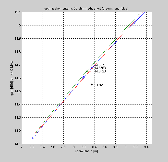
Figure 1 OMNEC simulations with interpolated gain for maximum gain designs. | |||||||||||||||||||||
|
By producing similar data like shown in figure 1 at different frequencies
we can produce the gain vs frequency curves for interpolated antennas
with the same boomlength as 2sa13.
The data is extracted from the RESULT.NEC files contained
in the .ZIP files above.
Figure 2 shows the comparison between 2sa13 and interpolated maximum gain
designs for the same boom length.
It is immediately clear that 2sa13 has much more bandwidth than
the maximum gain designs.
| |||||||||||||||||||
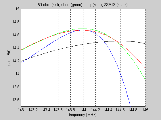
Figure 2 OMNEC simulations for 2sa13 compared to interpolated maximum gain designs of the same boom length. | |||||||||||||||||
|
To further illustrate the bandwidth problems with maximum
gain designs, fig 3 shows the impedance versus frequency for
the interpolated maximum gain designs (boom=8.35 m) compared
to the impedance curve of 2sa13.
The impedance is shown as normalised VSWR curves.
It is assumed that a lossless matching device is added to each
antenna to make the VSWR = 1.00 at 144.000 MHz.
| |||||||||||||||
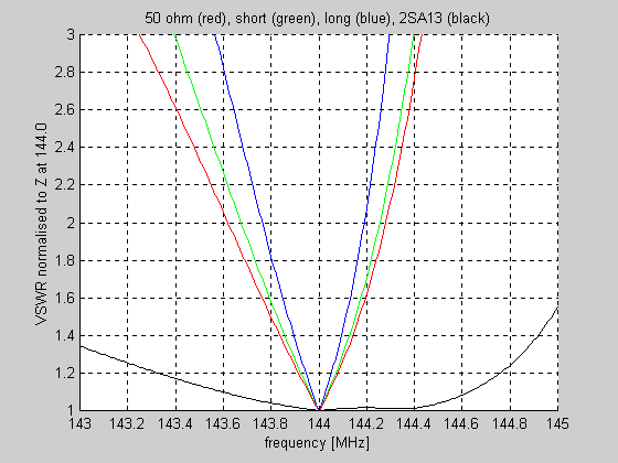
Figure 3 OMNEC simulations for 2sa13 compared to interpolated maximum gain designs of the same boom length. | |||||||||||||
|
Most amateurs would willingly accept a 0.25 dB loss of gain to get only the VSWR bandwidth advantage illustrated in figure 3. Among other things the 2sa13 bandwidth is obtained by asking OMNEC to optimise simultaneously at 144.0 and 144.3 MHz. Now the bandwidth is not the main trade off. A clean pattern, normally expressed as a single figure of merit G/T, is highly desirable. Fig 4 shows a comparison of G/T values at 8.35 meters boom length. We have used Tgnd=1000 K and Tsky=200 K and an elevation angle of 30 degrees was assumed. These parameters are generally used for comparisons at 144MHz. | |||||||||||
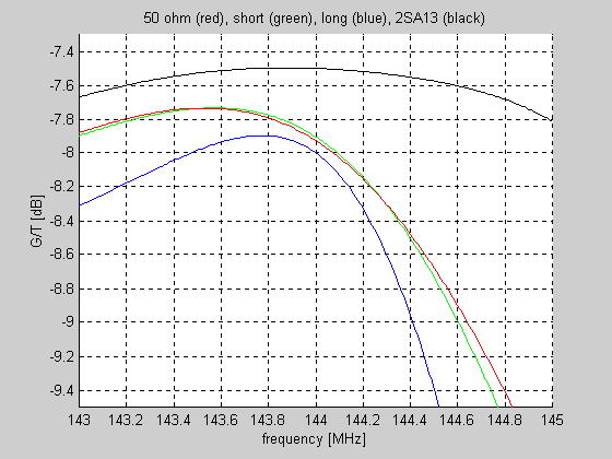
Figure 4 OMNEC simulations for 2sa13 compared to interpolated maximum gain designs of the same boom length. | |||||||||
|
Summing up the comparison between a single 2sa13 and hypothetical
maximum gain antennas of the same boom length we first should
note that the antennas use different numbers of elements:
Long (blue) 11 elements (at 8.19 m) Short (green) 12 elements (at 8.25 m) 50 ohm (red) 12 elements (at 8.30 m) 2sa13 (black) 13 elements (at 8.35 m) A maximum gain per element design, blue curves, is very critical and difficult to match because the impedance is far from 50 ohms. The Chen Cheng 6 element design is a well known example of this kind of antenna. For longer yagis one more element is no disadvantage because what we want is rather gain per boom length than gain per element. The red and green curves, still maximum gain per element because that is what OMNEC produces when all elements are free to move are very similar. The extra element gives much more flexibility which can be used to obtain 50 ohm feed impedance at practically no cost in gain or bandwidth. Such a design with 14 elements and 50 ohms feed impedance was used by Leif, SM5BSZ for six years 1993-1999 with good results. To be used with advantage this kind of antenna needs a rural area with a ground temperature close to 290 K and it has to be mounted at 45 degrees (X position) to avoid water on the elements in wet weather. The mounting is also critical and special care has to be taken to avoid degradation by influence of metal when using a maximum gain design. The 2sa13 is a high Q antenna. It is optimised for a fixed boomlength of 8.35 meters. It is selected as the best choice after a comparison of similar designs at other fixed boom lengths (step size 0.05m). Already on the comparisons between single antennas, as seen in the figures above, the 2sa13 is clearly an antenna to prefer over maximum gain designs. 2sa13 has a markedly better G/T than a maximum gain design. At the frequency of maximum gain a maximum gain antenna has 0.4dB lower G/T compared to 2sa13. The useful bandwidth of 2sa13 is about 10 times larger compared to a maximum gain design. Stacked antennas With the increasing use of computers amateurs experience more problems with interference. A clean pattern is more important today than 10 years ago and will most likely be even more so in the future. Some under-stacking in order to reduce side-lobes is often used. Some forward gain is then traded for a cleaner pattern. When an antenna is designed for some optimum compromise between gain and other desirable properties as a single antenna it is absolutely not sure that it will be a similarly good optimum when it is used in an under-stacked array. The 2sa13 is optimised as a 4x13 array in a symmetric configuration with a stacking distance of 4.2 meters. This is close to optimum gain stacking so the difference between optimising the antenna in stacked configuration rather than as a single yagi is small. Still there are subtle differences which make the four stack of 2sa13 at 4.2 meters an extremely good antenna for it's size. Figure 5 shows gain, G/T and VSWR for a symmetric 4-stack at 4.2 meters of the 2sa13 compared to a 4-stack of K1FO 14 element antennas stacked at 4.024 x 4.176 meters. The K1FO series of high-performance 144-MHz yagis is described in the ARRL HANDBOOK. (Page 33-29 in the 1994 edition) where they are claimed to be within 0.1 to 0.2 dB of the maximum theoretical gain. Theory has improved since this statement was made, but still the K1FO designs are very good and represent the state of the art in high gain 144MHz antennas before 2sa13. The comparison in figure 5 is slightly unfair to the 2sa13 because it is in a symmetric stacking configuration. In case the K1FO design is used for orthogonal polarisations (X-yagis) there will be a small loss because the same optimum stacking can not be used simultaneously for the two polarisations. The gain of 2sa13 is about 0.3dB higher compared to the K1FO design. The boom lengths are very similar 8.350 meters for 2sa13 and 8.352 meters for K1FO. G/T is 0.1 dB higher for 2sa13 compared to the K1FO design. The price we have to pay for the improvements is reduced bandwidth and a design that can not be changed by adding or subtracting one or a few tapered directors. The translation of the results of the mathematical model into a real world antenna is far more difficult for narrow band designs as 2sa13 compared to more conventional designs. Figure 6 shows how a single 2sa13 compares to a single 14 element K1FO antenna. Since the 2sa13 is not designed for understacking the differences are small when it is compared as a single antenna or as a four-stack. | |||||||
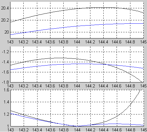
Figure 5 OMNEC simulations for four-stacks of 2sa13 and the K1FO 14 element design. | |||||
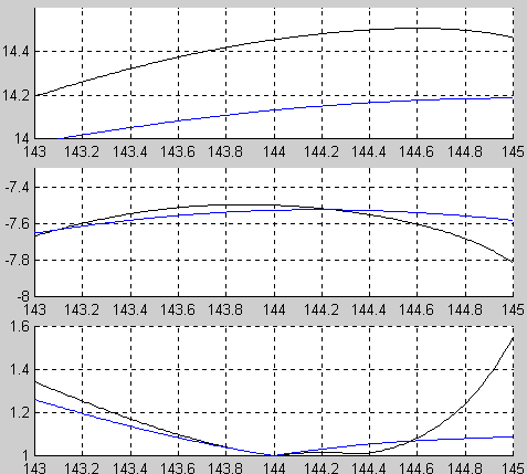
Figure 6. OMNEC simulations for 2sa13 compared to the K1FO 14 element design. | |
|
In case you want to look at the numeric data used for figures 5 and 6,
download these files:
K1FO 14 el 2sa13 4 x K1FO 14 el 4 x 2sa13 Each .ZIP file contains the following text files: INPUT.NEC (geometry of antenna, input to OMNEC ) PARNR.NEC (parameter numbering, input to OMNEC ) RESULT.NEC (OMNEC output. Gain, G/T and impedance 143 to 145 MHz ) FARFIELD.NEC (OMNEC output. Phase of far field 143 to 146 MHz ) Optimisation procedure The procedure we have followed to arrive at the NEC2 model for 2sa13 is as follows: 1. Select a maximum gain design of suitable size and select a suitable starting stacking distance a few tenths of a dB below maximum stacking gain. 2. Identify the most important undesired property of the design. Select between those properties for which a parameter value is not yet determined. 3. Step the parameter that affects the property found in step 2 and re-optimise. Select the parameter value that gives the best improvement of the overall performance. If a new parameter value is found to be better than the old, note this parameter as determined and note all the others as not yet determined. In case any parameter is not yet determined go to step 2 4. Try to insert one more element near the driven element and re-optimise. If the element is not moved into another element or removed by becoming very short, flag all parameters as not yet determined and go to step 2. By selecting a boom length where one element nearly, but not quite wants to remove itself some extra bandwidth can be obtained. In the 2sa13 design the first director is kept 100 mm in front of the radiator for practical reasons and because we fear NEC2 is not accurate enough to be used for correct impedance at closer spacings. In the optimisation process we use an extended definition of the concept of parameters as defined below (roughly in order of significance): 1. Frequency If the bandwidth is too small the FR line of the NEC input can be used to specify optimisation simultaneously at several frequencies. 2. Fixed boom length Longer booms give more gain but what is considered optimum is up to the designer. Gain per boomlength is not much affected but the bandwidth depends on this parameter. 3. Stacking distance Affects gain and side-lobe levels. If the array is large enough for the side lobes to fall within 30 degrees, G/T is not much affected. 4. Z(voltage) When the elements are excited by a voltage step function as in all examples on this site, this parameter affects the deviation of the impedance from the desired impedance. 5. G/T This parameter improves G/T as calculated by the parameters specified in the input files. (default is Tsky=1000, Tgnd=290, El=30deg) The main lobe becomes wider and the side-lobes become smaller when this parameter is increased. 6. Element diameter Larger element diameters reduce ohmic losses and improve bandwidth. The directors near the radiator carry the highest currents and there is an advantage in making them thick. The directors further away are less sensitive and it may be a good idea to make them thinner to reduce wind load far from the support point. The reflector is also uncritical. The 2sa13 has a thick radiator for mechanical reasons, not to improve the bandwidth. The current in the radiator is small (Z = 50 ohms!!) 7. Efficiency This parameter can be used to reduce the ohmic losses. The reduced currents that is a consequence give more bandwidth and less gain. It is a good idea to use this parameter for a small loss of gain. The antenna is then less sensitive to increased ohmic losses due to ageing or water on the elements. 8. Back lobeThe radiation at 180 degrees is more disturbing in practical use of an antenna than indicated by the G/T value when it comes to terrestrial modes. The 180 degree lobe has a very small solid angle so it does not affect gain or G/T much. Therefore it may become rather strong if this parameter is not used. Reducing the 180 degree lobe usually has very small effects on other characteristics. Be careful to not introduce this parameter before all the others have converged reasonably well. Forcing a null at 180 degrees may be harmful to the convergency of the optimisation process leading to a false optimum. Optimisation parameters The following parameter values were used in the final optimisation process leading to the 2sa13 design: Z(voltage) = 0.07 Efficiency = 0.025 Back lobe = 0.5 G/T = 0.03 Frequency = 144.0 and 144.3 MHz Stacking distance = 4.2 meters Fixed boom length = 8.35 meters Element diameter = 10mm for elements 2 to 6, 6mm for others. The selection of these parameters is in no way critical. If you want to study how variations of these parameters affect the final result, use 4x2sa13.ZIP which contains OMNEC input files and run OMNEC. If a parameter is changed, OMNEC will produce a different optimum. Note that the number of segments is large on all elements and that gain and G/T are calculated with a very fine mesh with these input files. It is a good idea to use fewer segments on the GW lines and fewer steps in the RP line of INPUT.NEC when searching for other designs and to increase the accuracy gradually when the result (your parameter choice) converges. Check different numbers of segments (GW:NS) and steps in both theta and phi (RP:NTH and NPH) and do not use more than required for the accuracy required to see the influence of changing the parameters. It is a good idea to make a final (very slow) optimisation with very high accuracy to find the true minimum for the selected set of parameters. If you prefer some other compromise over 2sa13 or if you want to use different boom tubes you may use the boom corrections from BC to make the optimum antenna of your own choice. |